 AI Video Guide
  AI Picture Guide
 AI One Sentence

Heming Hu, Yafang He, Baisong Chen, Ziming Wang, Yingzhi Li, Qijie Xie, Quanxin Na, Zihao Zhi, Xuetong Li, Huan Qu, Patrick Lo, Junfeng Song, "Silicon-based optical phased array with a reconfigurable aperture for “gaze” scanning of LiDAR," Photonics Res. 12, 932 (2024)
- Photonics Research
- Vol. 12, Issue 5, 932 (2024)
Note: This section is automatically generated by AI . The website and platform operators shall not be liable for any commercial or legal consequences arising from your use of AI generated content on this website. Please be aware of this.
Abstract
1. INTRODUCTION
Light detection and ranging (LiDAR) technologies have been widely applied in autonomous driving, environment detection, sensing, etc. [1]. In these applications, all solid-state LiDAR systems have been attracting good attention for their compact size and high robustness [2,3]. Therefore, it has been considered as a promising solution for beaming and steering to supersede the bulky traditional mechanical beam steering. In recent years, various non-mechanical beam-steering methods have been proposed, including micro-electro-mechanical system (MEMS) mirrors [4–6], flash LiDAR [7–9], lens-assisted beam steering (LABS) [10–14], liquid crystal [15–17], and optical phased array (OPA) [18,19]. However, some basic limitations emerge while solving the problem of mechanical beam steering. The MEMS mirror suffers from a limited steering speed as well as the potential problem of mechanical fatigue. Flash LiDAR has a short detection range. For LABS, the scanning angles are discrete rather than continuous. Besides, if there is a need to increase the number of scanning points, the scale of the optical switch would need to be increased exponentially. Currently, OPA-based steering has attracted increasing attention for its advantage of compact size, low power consumption, low cost, and compatibility [20] with standard CMOS processes; it can be expected for the on-chip optoelectronic hybrid LiDAR system in the future [21]. Based on the above reasons, various OPA devices have been explored with different features and merits [22,23], including the power optimization in phase shifters [24,25], the enhancement of grating emission energy [26,27], the increasement of main lobe power [28,29], and the design of transceiver systems [30].
The angular resolution stands as a crucial parameter for OPA devices. A high angular resolution is constructive to accurate detection of a target object. An effective way to improve resolution of OPA is by reducing the divergence angle. Theoretically, a small divergence angle can be achieved by increasing the effective aperture. Currently, there are typically two approaches to enlarge the effective aperture of the OPA. One method is to increase the quantity of antennas within the OPA. Currently, the state-of-the-art OPA chips can provide up to 8192 available channels [30–32]. However, as the number of channels increases, the complexity of system control grows proportionately. It imposes stringent demands on the OPA control circuit, since precise calibration voltages need to be applied to all channels for beam steering. Besides, as the number of OPA channels increases, the power consumption grows exponentially. It would degrade the stability and life-span of the overall system. The other method to increase the effective aperture is by utilizing an OPA with non-uniform antenna pitch [33,34]. By employing a non-uniform antenna pitch distribution, the effective aperture of the OPA can be greatly increased, resulting in a smaller divergence angle and a wider field of view. However, a portion of the main lobe power and grating lobe power is allocated to side lobes, leading to signals being overwhelmed by the noise-like side lobe during long-distance detection [33]. In addition, blindly increasing the aperture size will lead to an increase in its far-field distance [33,35–37]. Targets within the distance forming the far-field beam cannot be effectively detected, resulting in a blind zone in the field of view. Besides, for the OPAs used in LiDAR applications, not all targets within the field of view are of interest. Hence, much of the distance information in the scanning area is redundant. It can be anticipated that utilizing high resolution to scan across all areas uniformly would result in increased detection complexity, reduced scanning rate, and higher power consumption.
The issues mentioned above can be addressed through adaptive control of the OPA’s aperture. Specifically, the aperture size can be determined flexibly according to the desired detection range, scanning precision, and scanning frame rate. In particular, a small aperture is applied in the case of close-range detection for a wide field of view, while a large aperture is used in long-range detection with high transmit-receive power and beam precision. So far, most reported OPAs can only provide fixed divergence angles at the given apertures. Although there are examples of using optical switches to select transmitting antennas [38,39], the purpose is to splice the scanning range in the longitudinal direction by altering the period of the grating, which does not essentially change the aperture size of the OPA.
Sign up for Photonics Research TOC. Get the latest issue of Photonics Research delivered right to you!Sign up now
In this work, we have demonstrated a novel LiDAR structure based on an OPA with reconfigurable apertures. By virtue of the cascaded optical switch, 64-channel, 128-channel, 192-channel, and 256-channel antenna apertures can be switched readily. The corresponding beam divergence angles of OPA can be 0.32°, 0.15°, 0.10°, and 0.08°, respectively. By switching apertures, the far-field distance of the OPA can be changed. This capability helps mitigate the impact of far-field distance on close-range detection and shorten the blind zone, simultaneously. Furthermore, the reconfigurable aperture of the optical phased array is proposed to achieve the gaze scanning function of LiDAR. The function is to perform an initial rough scan of the full field using a small aperture, followed by a fine scan of the target using a larger aperture. Through this approach, both rough scanning with full-range coverage and fine scanning of specific targets can be obtained. Moreover, this approach substantially reduces scanning power consumption and beam steering time. Finally, the reconfigurable aperture OPA is embedded into an FMCW system. To explore the impact of aperture variations on the LiDAR system, a target 2 m away is detected across different apertures. Experiment shows that apertures on one OPA detecting the same target will not distort the distance information. Through this system, we have demonstrated the gaze function in actual scanning. Experiment results indicate that the needed number of fine scanning points can be reduced by 2/3 to obtain the complete outline of the target.
2. STRUCTURE AND CHARACTERISTICS
The designed chip is manufactured in AMF. Figure 1(a) shows the optical microscope image of the fabricated reconfigurable-aperture OPA (RA-OPA). The chip includes a mode size converter, a
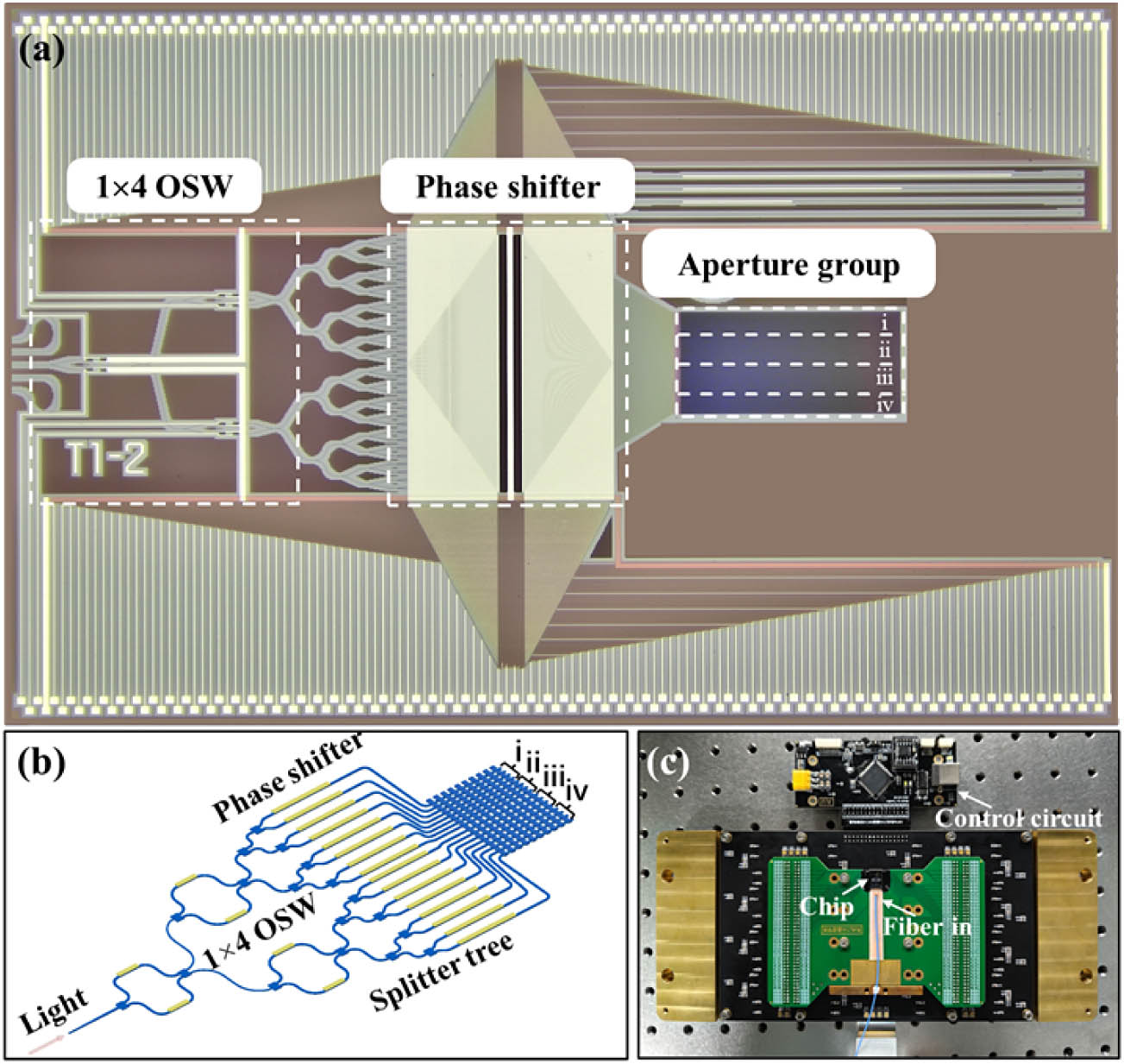
Figure 1.(a) Optical microscope image of the variable aperture OPA. (b) Schematic of the variable aperture OPA. (c) Electrically and optically packaged variable aperture OPA chip with control circuit.
As shown in Fig. 1(a), the aperture group consists of four parts as sub-apertures. Each sub-aperture receives signal through the output channel of the optical switch. As shown in Fig. 1(b), the OPA antenna array is divided into four groups labeled by i, ii, iii, and iv. Each group of antennas contains 64 channels, which are eventually combined being a 256-channel large-scale aperture. The antenna pitch is 4 μm and thus the summed aperture of the whole OPA is 1.02 mm. The design of the grating antenna follows the previous work [27]. The fishbone grating antenna with high emission efficiency is formed through an upper and lower double-layer etching process. The grating has a period
The optical switch embedded in the OPA chip consists of a
![]()
Figure 2.Schematic diagram of optical path distribution for OPA with (a) 64, (b) 128, (c) 192, and (d) 256 antennas.
As shown in Fig. 2(a), to ensure the light directed to an output of the OSW2, control voltages are applied to the OSW1 and OSW2 simultaneously, Consequently, there is no light put into OSW3, so its operational state can be disregarded. Under this optical path configuration, only one sub-aperture of the OPA can receive the optical signal and the 64-channel grating antenna array within the aperture serves as the light transmission. As shown in Fig. 2(b), when further increasing the transmitting aperture to a 128-channel grating antenna array, only the phase in OSW2 needs to be adjusted to eliminate the phase difference between the two phase shifters. In this operational state, the optical signals are distributed to output equally, ensuring that two adjacent cascaded beam splitters receive equal optical power. Ultimately, this forms the OPA with a 128-channel grating as the transmitting aperture. Furthermore, as the aperture of the OPA needs to be expanded to 192 channels, the phases of OSW1 and OSW3 are adjusted to distribute the light into three cascaded splitters evenly. The optical path distribution, as shown in Fig. 2(c), depicts a 2/3 connection ratio from OSW1 to OSW2 and a 1/3 connection ratio from OSW1 to OSW3. For OSW3, all the light needs to be output through the channel adjacent to OSW2’s output channel. Finally, in order to utilize all channels within the OPA for maximum aperture output, uniform optical intensity needs to be achieved across all splitters. By controlling the phase shifters in OSW1, OSW2, and OSW3 simultaneously, we can eliminate the phase differences in these three optical switches. The light signals are split equally among the four output channels, enabling the OPA’s 256 channels to function as a single aperture to maximize antenna scalability.
After selecting the required aperture through the optical switch, linear phase modulation is applied to the opened channel. Different sub-apertures will form an overall aperture and generate a far-field interference spot due to linear phase distribution. As shown in Fig. 2, when more channels are turned on, the aperture size will increase, and the corresponding divergence angle will decrease, resulting in a higher resolution of an OPA. The fewer the open channels, the fewer waveguides required to modulate the phase, and the simpler the system.
3. EXPERIMENT RESULTS
A. Characterization of the OPA Chip
The far-field beam formations at 0°,
![]()
Figure 3.Beam steering performance of (a) 64, (b) 128, (c) 192, and (d) 256 channels at 0°,
The light spot and cross-sectional curve of the main lobe along
![]()
Figure 4.Main lobe divergence at 0° with different aperture scales.
Beam steering requires precise assignment of phase to each channel, which needs independent voltage control of phase shifters above the waveguides. By reading the voltage and resistance of channels, the actual power consumption of each channel can be calculated, and the overall power consumption of the OPA chip will be obtained by accumulating it. Through this method, the OPA power consumption under different apertures is analyzed in detail. As shown in Fig. 5, the power consumption required for beam steering under different apertures is calculated, and the average power consumption required under each aperture is analyzed. The power consumption with various angles is measured at a wavelength of 1550 nm, where the lateral scanning angle is from
![]()
Figure 5.(a) Power consumption required for steering under different apertures within the range of
In addition, the retarding time for turning on all operation channels is critical for agile beam steering. In our work, we evaluate the required time for turning on the last channel of the 64-, 128-, 192-, and 256-channel OPAs. The measured results of the 64th channel, the 128th channel, the 192nd channel, and the 256th channel are shown in Figs. 6(a), 6(b), 6(c), and 6(d), respectively. It illustrates that the large-channel-scale OPA requires a longer waiting time. This results in an increase in the overall time to configure voltages across all channels as the channel count rises. This incremental time slows down the OPA beam steering rate and thus the frame rate of the LiDAR system.
![]()
Figure 6.Configuring the voltage for (a) 64, (b) 128, (c) 192, and (d) 256 channels at the same time, and the turn-on time of the last channel.
B. Far-Field Distance of the OPA Chip
The far-field distance is crucial to the minimum detection distance. For a typical far-field condition to be satisfied, the distance of the observation needs to meet the following condition [35]:
In this work, we propose an OPA with a reconfigurable aperture to avoid the blind zone effectively. Figure 7 shows the required propagation distance for the side lobe suppression ratio to reach
![]()
Figure 7.Far-field distance for different apertures.
To analyze this issue, simulation and experiment are systematically applied under different apertures. Figure 8(a) describes the formation process of the main lobe with distance under different aperture sizes. Figure 8(b) shows the actual spot pattern measured by a near-infrared camera at different distances and different apertures. It shows that as the number of antennas grows, the length of beamforming becomes notably longer. For further analysis, the beam spots formed at three representative distances, [i] 3 cm, [ii] 10 cm, and [iii] 20 cm, are compared. As illustrated by the row [i] in Fig. 8(b), only the 64-channel aperture shows a clear main lobe, while the 128-channel, 192-channel, and 256-channel apertures have not yet reached the far-field distance. Hence, multiple peaks are generated at the position of the main lobe. In particular, six different intensity spots appear in the case of the 256-channel aperture, mainly resulting from the long beamforming distance. As the detection distance increases to 10 cm, the 128-channel aperture also exhibits a distinct main lobe. Meanwhile, although the 192-channel aperture shows the main lobe as well, undesired side lobes are also observed. The beam pattern may cause interference in detection due to strong side lobe power at this distance. In addition, for the 256-channel aperture, the number of light spots is reduced, indicating a trend toward main lobe formation. Finally, as the detection distance reaches 20 cm, distinct main lobes for all apertures are well observed. As shown in the row [iii] of Fig. 8(b), the light spots of the 64 channels, 128 channels, and 192 channels further compress and exhibit normal beam quality under this distance. Hence, by selecting appropriate emission apertures for different distances, significant reduction in the blind zone can enhance the detection performance of the OPA.
![]()
Figure 8.(a) Simulated formation process for light beams of 64-, 128-, 192-, and 256-channel OPA along with distance; (b) captured beam spot at the distance of 3 cm, 10 cm, and 20 cm.
C. Gaze Scanning Function Enabled by the RA-OPA
High points density leads to accurate restoration of an actual scene. The resolution of a point cloud is closely related to the aperture size of OPA. However, most reported OPAs are designed with fixed apertures, so their resolution and scanning frequency frame rate are fixed at the time of manufacture. Besides, high-density point cloud scanning is often power and time consuming. Hence, rich scanning details normally compromise scanning frame rate. By physically altering the aperture size of OPA, the LiDAR “gaze” scanning function balances scanning points and frame rates. As illustrated in Fig. 9, in the “gaze” mode, OPA with a small aperture is used to scan the frontal area with sparse scanning points, while the large aperture is used to enhance the point cloud resolution, so that richer details in the ROI can be perceived. This methodology resembles the way that the human eye “gazes” at an object. It ensures the OPA point cloud frame rate while also considering the details within the ROI.
![]()
Figure 9.Schematic diagram of gaze scanning using different apertures.
To introduce the gaze function, 64-channel and 256-channel apertures are used for demonstration. As shown in Figs. 10(a) and 10(b), the measured far-field patterns of 64-channel and 256-channel apertures over 20° are exhibited, respectively.
![]()
Figure 10.Sum of the normalized far-field spot obtained by the (a) 64-channel aperture and (b) 256-channel aperture steering with laser wavelength and phase shift.
Since the divergence angle of the 64-channel aperture is four times that of the 256-channel aperture, the 64-channel and 256-channel apertures are scanned at steps of 0.8° and 0.2°, respectively. Light points are displayed in the
The performance of the RA-OPA is tested with gaze scanning. Figure 11(a) displays a picture of the scanned letters “JLU.” As depicted in Fig. 11(b), a rough scan of the JLU letters was achieved by switching to the 64-channel aperture. The rough position of the letters can be perceived. It can be found that only one to two detected points are observed on each letter. Then, without changing the background scanning resolution, the three letters “JLU” are accurately scanned by the same OPA chip switched to the 256-channel aperture. As shown in Fig. 11(c),
![]()
Figure 11.(a) Picture of the letters JLU as a scanning target; (b) full-range scanning using 64-channel aperture; (c) gaze on the letters
D. RA-OPA Embedded FMCW LiDAR Ranging
By using the proposed OPA, a frequency-modulated continuous-wave (FMCW) ranging system is demonstrated. The schematic of FMCW LiDAR circuit is illustrated in Fig. 12. The OPA is added to the system as a transmitter (TX) and a beam collimator is added as a receiver (RX) in the system. A single wavelength laser is modulated by the single sideband (SSB) modulator to generate a modulated triangular optical signal. The modulation bandwidth is 3 GHz. The modulated signal is amplified by the erbium-doped fiber amplifier (EDFA). The amplified light is distributed into a local oscillator (LO) signal and TX signal at a ratio of 0.1:0.9. The TX signal is coupled into the OPA for scanning. The reflected light is received through a collimator and coherently beaten against the LO. A balanced detector containing a transimpedance amplifier (TIA) converts the light signal into voltage signal, and the multichannel high-speed analog-to-digital converter (ADC) reads the voltage signal, which can be analyzed by digital signal processing (DSP). The generated beat frequency is proportional to the target distance. The target distance is given by
![]()
Figure 12.Schematic diagram of RA-OPA embedded FMCW LiDAR system.
The ranging uniformity of OPA with different apertures is measured. The experimental setup is depicted in Fig. 13(a). Figures 13(b)–13(e) illustrate RF spectra for beat signals in the cases of OPA with 64-channel, 128-channel, 192-channel, and 256-channel apertures. The steering angle is 0° and the distance is 2 m. As can be seen from the figure, using different apertures on one OPA to detect the same distance target will not distort the distance information. The peak frequencies detected across all apertures are 2.083 MHz. However, the signal-to-noise pedestal ratios (SNPRs) vary under different apertures. The SNPRs for 64-channel, 128-channel, 192-channle, and 256-channle apertures are
![]()
Figure 13.(a) Picture of experimental setup. RF spectra for the beat signal in the cases of (b) 64-channel, (c) 128-channel, (d) 192-channel, and (e) 256-channel OPA at a distance of 2 m.
To demonstrate the gaze function of RA-OPA, a one-dimensional object scanning was conducted. In the following measurements, three targets are placed at distances of 1.7 m from the OPA, as shown in Fig. 14(a). The length of each side of the square is 20 cm, the vertex angle of the isosceles triangle is 30°, and the side length is 20 cm. The upper base of the isosceles trapezoid is 10 cm, and the lower base is 30 cm. The side lengths of the left and right sides are 20 cm, and the angle between the upper base and the side is 120°. The gap between the three objects is 10 cm.
![]()
Figure 14.(a) Picture of targets placed in front of the OPA in different directions; (b) experimental result for a rough scan of the target by using 64-channel aperture; (c) experimental result for a fine scan of the target by using 256-channel aperture; (d) gaze at the corner of the target using 256-channel aperture; and (e) target position information obtained by splicing rough scan and gaze areas.
Three scanning methods are used on the object. Figure 14(b) shows a rough scan using the OPA with a 64-channel aperture at a step of 1° to capture the basic outline of the objects. This scan clearly shows surface outlines including the front of the square, edges of the trapezoid, and the background. However, due to the larger scanning angle, details at the corners and the triangle could not be detected. Under this scanning, only 27 points are required. Similarly, a precise scanning of a three-project outline is shown. Figure 14(c) shows the precise outline of the object captured through 256 apertures in a step of 0.2°. In this scanning method, all details of the object can be obtained, including the vertices of triangles, the two vertex angles of trapezoids, etc. However, the higher resolution causes wasted detail for the square’s front and background. The number of points required for this precise scan is 269, significantly increasing the scanning complexity. This problem can be addressed by using a gaze function. As shown in Fig. 14(d), details missed by the rough scan can now be detected by focusing on the corner positions of the target objects. Finally, by splicing all the data from both the rough and gazed scans, a one-dimensional profile of the object comparable to a high-precision scan is obtained in Fig. 14(e). Based on this method, only 80 points are needed, with 27 from rough scanning and 57 from fine scanning—just one-third of the points needed for the high-resolution scan. This method greatly reduces the scanning time and complexity.
4. CONCLUSION
In conclusion, we have demonstrated an OPA with a reconfigurable aperture from 64 to 256 channels. Attributed to the
For the current microwave photonic radar, it can already realize the function of detecting and tracking multiple targets with a single aperture [40–42]. However, the developed OPA-based LiDAR is still at the stage of single target detection. This is mainly limited by the fact that OPA LiDAR uses a single light source and an overall controlled phase modulation system. Although silicon photonic chips are easy for on-chip integration, multiple independent OPA chips can be integrated on one chip with independent light sources and phase control, and ultimately achieve the purpose of focusing on multiple targets at the same time. However, multi-target scanning with OPA under a single aperture is still a very challenging task needing further study.
References
[2] M. X. Hu, Y. Pang, L. Gao. Advances in silicon-based integrated LiDAR. Sensors, 23, 5920(2023).
[37] W. H. Xu, C. Liu, Y. Guo. Impact of aperture size on beam evolution of optical phased arrays. Optical Fiber Communications Conference and Exhibition (OFC), 1-3(2021).
[42] X. P. Liu, K. Wang. Research on high-resolution wide-swath SAR based on microwave photonics. CIE International Conference on Radar (RADAR), 1-3(2016).


Set citation alerts for the article
Please enter your email address

© Copyright 2018-2021 | Chinese Laser Press. All Rights Reserved 沪ICP备15018463号-20