• Chinese Optics Letters
  • Vol. 21, Issue 4, 041403 (2023)
Qing Ye1、2, Yunlong Wu1、2、**, Hao Zhang1、2、*, Yangliang Li1、2, Lei Wang1、2, and Ke Sun1、2
Author Affiliations
  • 1State Key Laboratory of Pulsed Power Laser Technology, National University of Defense Technology, Hefei 230037, China
  • 2Advanced Laser Technology Laboratory of Anhui Province, Hefei 230037, China
  • show less
    DOI: 10.3788/COL202321.041403 Cite this Article Set citation alerts
    Qing Ye, Yunlong Wu, Hao Zhang, Yangliang Li, Lei Wang, Ke Sun. Experimental damage thresholds of a laser suppression imaging system using a cubic phase plate[J]. Chinese Optics Letters, 2023, 21(4): 041403 Copy Citation Text show less
    Sketch of the wavefront coding imaging system.
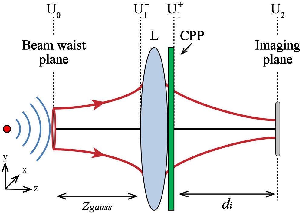
    Fig. 1. Sketch of the wavefront coding imaging system.
    Spot profile and corresponding maximum single-pixel receiving power without defocus at the imaging plane of (a) conventional imaging system at the transmission distance of 38 m; (b) CPP wavefront coding imaging system at the transmission distance of 38 m; (c) conventional imaging system at the transmission distance of 2500 m; and (d) CPP wavefront coding imaging system at the transmission distance of 2500 m.
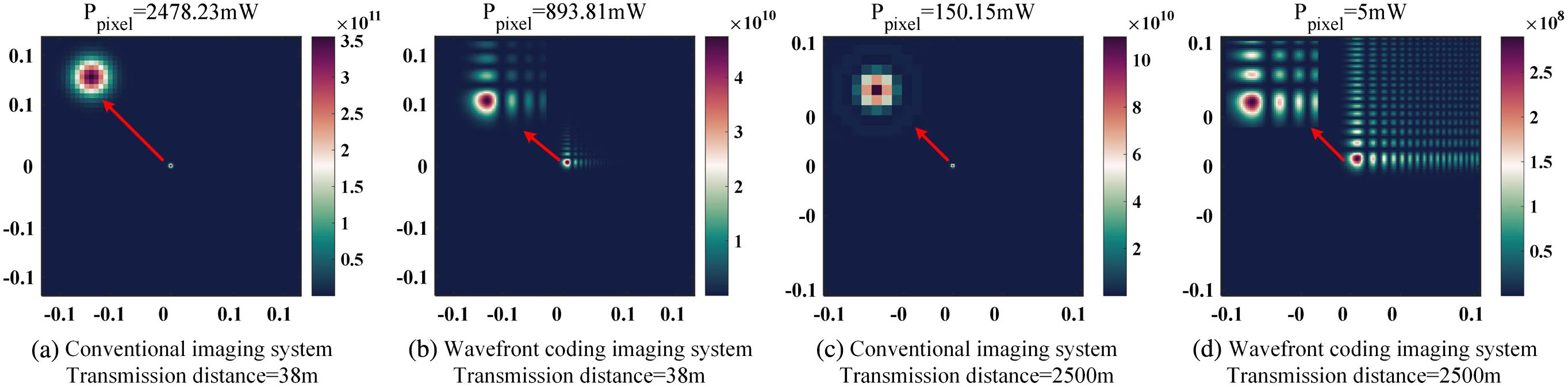
    Fig. 2. Spot profile and corresponding maximum single-pixel receiving power without defocus at the imaging plane of (a) conventional imaging system at the transmission distance of 38 m; (b) CPP wavefront coding imaging system at the transmission distance of 38 m; (c) conventional imaging system at the transmission distance of 2500 m; and (d) CPP wavefront coding imaging system at the transmission distance of 2500 m.
    Ratio of maximum single-pixel receiving power between the conventional and the wavefront coding imaging systems.
    Fig. 3. Ratio of maximum single-pixel receiving power between the conventional and the wavefront coding imaging systems.
    Sketch map of the experimental optical setup.
    Fig. 4. Sketch map of the experimental optical setup.
    Design of wavefront coding lens. (a) Schematic diagram of disassembly structure; (b) aperture stop with integrated CPP; (c) CPP component; (d) modulation function of CPP.
    Fig. 5. Design of wavefront coding lens. (a) Schematic diagram of disassembly structure; (b) aperture stop with integrated CPP; (c) CPP component; (d) modulation function of CPP.
    Pulsed laser-induced damage of CMOS sensor in (a1)–(a3) conventional imaging system and (b1)–(b3) wavefront coding imaging system; (a1) and (b1) for spot damage; (a2) and (b2) for line damage; (a3) and (b3) for full screen damage.
    Fig. 6. Pulsed laser-induced damage of CMOS sensor in (a1)–(a3) conventional imaging system and (b1)–(b3) wavefront coding imaging system; (a1) and (b1) for spot damage; (a2) and (b2) for line damage; (a3) and (b3) for full screen damage.
    Pulsed laser-induced damage of CCD sensor in (a1)–(a3) conventional imaging system and (b1)–(b3) wavefront coding imaging system; (a1) and (b1) for spot damage; (a2) and (b2) for line damage; (a3) and (b3) for full screen damage.
    Fig. 7. Pulsed laser-induced damage of CCD sensor in (a1)–(a3) conventional imaging system and (b1)–(b3) wavefront coding imaging system; (a1) and (b1) for spot damage; (a2) and (b2) for line damage; (a3) and (b3) for full screen damage.
    ParametersValue
    Laser beam waist4 mm
    Distance from waist to entrance pupil38 m
    Laser power5 W
    Laser wavelength532 nm
    Focal length of imaging system50 mm
    Imaging lens pupil size∅25 mm
    Image plane detector pixel size3.3 µm × 3.3 µm
    Table 1. Simulation Parameters
    Qing Ye, Yunlong Wu, Hao Zhang, Yangliang Li, Lei Wang, Ke Sun. Experimental damage thresholds of a laser suppression imaging system using a cubic phase plate[J]. Chinese Optics Letters, 2023, 21(4): 041403
    Download Citation