
Qing Ye, Yunlong Wu, Hao Zhang, Yangliang Li, Lei Wang, Ke Sun, "Experimental damage thresholds of a laser suppression imaging system using a cubic phase plate," Chin. Opt. Lett. 21, 041403 (2023)
- Chinese Optics Letters
- Vol. 21, Issue 4, 041403 (2023)
Abstract
1. Introduction
Over the past decade, laser systems have become more and more powerful, low-priced, and compact[1,2]. Intense laser radiation is increasingly becoming a hazard to electro-optical imaging sensors, since complementary metal–oxide semiconductor (CMOS) or charge-coupled device (CCD) imaging sensors are very sensitive to high-intensity light fluxes from lasers[3,4]. High-power lasers may temporarily disrupt image acquisition, or even damage the optical sensor by excessively illuminating the sensor. To overcome this issue, protecting imaging sensors against dazzle and damage by laser radiation has become an ongoing research domain[5,6]. Optical filters based on absorption or interference effects and nonlinear window materials have been proposed to mitigate the threat of laser damage[5,7–9]. However, existing sensor protection schemes exhibit many limitations, such as spectral range, image fidelity, and response time[7]. Recently, computational imaging has been widely applied in many fields. Wavefront coding imaging is one of the computational imaging technologies, which includes a phase mask in the pupil plane of the optical system; it can achieve high-quality imaging along with a wide range of defocus through digital processing[10–12]. Swartzlander et al. used vortex and axicon phase masks in the pupil plane of the wavefront coding imaging system to modify the point spread function (PSF) of the optical system, thereby reducing the peak irradiance on the sensor[13,14]. Although this approach blurs the image, it can be recovered through Wiener deconvolution in postprocessing[13,14]. This technique requires no absorption mechanism and offers an instantaneous response time. However, existing research has not investigated and compared the morphology of laser-induced damage on different imaging sensors and has not examined the laser damage thresholds of different imaging sensors experimentally in conventional imaging systems and developed laser suppression imaging systems.
This paper proposes a laser suppression imaging technique based on cubic phase plate (CPP) wavefront coding to reduce the risk of laser damage. For wavefront coding imaging systems, the CPP can increase the focal depth range of the optical systems and can produce an intermediate coded image that is insensitive to defocusing. Based on the wavefront coding imaging model, the diffracted spot profile distribution and the light intensity distribution on the observation plane are simulated. This paper also studies the antilaser damage performance of the CPP wavefront coding imaging system under different propagation distances. An experimental device is set up to investigate the morphology of laser-induced damage patterns on the laser pulse energy. In addition, we experimentally measure the laser damage thresholds of CMOS and CCD sensors in wavefront coding and conventional imaging systems. Simulation and experimental results preliminarily manifest the superior antilaser damage performance of the CPP wavefront coding imaging system.
2. Theoretical Modeling
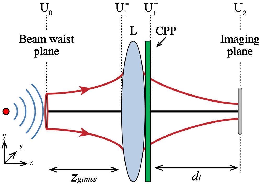
Figure 1 illustrates a sketch of the wavefront coding imaging system. The optical system consists of a CPP in the pupil plane of the imaging system to modulate the incoming light. The formation of the amplitude distribution on the imaging plane is recorded as follows.
Sign up for Chinese Optics Letters TOC. Get the latest issue of Chinese Optics Letters delivered right to you!Sign up now
![]()
Figure 1.Sketch of the wavefront coding imaging system.
Suppose the Gaussian beam whose beam waist is
Assuming that the CPP is close to the rear surface of L, they can be regarded as a single component whose transmittance function can be expressed as
The complex amplitude distribution on the rear surface of the CPP is calculated as
3. Simulation Results
This section provides a set of simulations to assess the antilaser damage performance of the wavefront coding imaging system based on the CPP. When CMOS and CCD work, they receive light through the photosensitive surface to generate a photoelectric effect, and the optical signal is converted into an electrical signal[19]. When the irradiation light intensity is excessive, CMOS and CCD may be saturated or even damaged. Since the photodetector generates and transfers charge in pixel units, we use the maximum single-pixel receiving power as the evaluation index to compare the antilaser damage performance of the wavefront coding and conventional imaging system.
Figure 2 shows the spot profile distribution and corresponding maximum single-pixel receiving power
| Parameters | Value |
|---|---|
| Laser beam waist | 4 mm |
| Distance from waist to entrance pupil | 38 m |
| Laser power | 5 W |
| Laser wavelength | 532 nm |
| Focal length of imaging system | 50 mm |
| Imaging lens pupil size | ∅25 mm |
| Image plane detector pixel size | 3.3 µm × 3.3 µm |
Table 1. Simulation Parameters
![]()
Figure 2.Spot profile and corresponding maximum single-pixel receiving power without defocus at the imaging plane of (a) conventional imaging system at the transmission distance of 38 m; (b) CPP wavefront coding imaging system at the transmission distance of 38 m; (c) conventional imaging system at the transmission distance of 2500 m; and (d) CPP wavefront coding imaging system at the transmission distance of 2500 m.
As shown in Fig. 2, for the conventional system a distant laser source is focused onto the focal plane of the optical system converging into one energy concentrated light point that may cause laser dazzle across the photodetector. For the wavefront coding imaging system, the spot on the imaging plane detector is L-shaped and nonrotationally symmetric due to the modulation of the CPP. The maximum single-pixel receiving power in the conventional imaging system is 2.77 times higher than in the wavefront coding imaging system when the laser propagation distance is 38 m. It can be observed from Fig. 2 that the redistribution of the light spot energy can reduce the maximum single-pixel receiving power, thereby improving the laser-suppression performance of the wavefront coding imaging system.
This paper next explores the influence of the propagation distance on the laser-suppression performance of the wavefront coding system. Figure 3 shows the ratio of the maximum single-pixel receiving power
![]()
Figure 3.Ratio of maximum single-pixel receiving power between the conventional and the wavefront coding imaging systems.
When the propagation distance varies from 1 to 1000 m, the ratio of the maximum single-pixel receiving power
To sum up, the CPP in the wavefront coding system can modulate the spot shape and redistribute the light spot energy on the imaging plane detector, thus reducing the maximum single-pixel receiving power. Simulation results sufficiently manifest the superior laser-suppression performance of the wavefront coding imaging system.
4. Experimental Setup and Results
An experimental system is designed and set up to investigate laser-induced damage and test suppression capabilities of the wavefront encoding imaging system in the laboratory. The sensors under test are irradiated by pulsed lasers to perform the laser-induced damage tests. The pulsed laser system we use is a spatial Gaussian energy distribution Nd:YAG laser, operating at a wavelength of 1064 nm with a maximum pulse energy of 1200 mJ and pulse duration of 10 ns. We use the second-harmonic at a wavelength of 532 nm, generated by a harmonic generating assembly. The experiment is performed using MICRON OV2710 monochromatic CMOS sensors with a resolution of
The sketch map of the experimental setup is shown in Fig. 4. The laser beam produced by the pulsed laser system propagates to the total reflectors A and B, successively. Then, the laser beam propagates to the thin-film beam splitter. While one beam split is reflected and detected by a power meter to monitor the energy of the incident pulse laser, the other split is expanded by a telescope system and then enters the conventional or wavefront coding imaging system as the light source of the damage experiment. The expanding system is used to expand the transmission distance of laser for the limited space in the laboratory. The laser equivalent transmission distance is 38 m. Before the experiment, the pulse energy at the sampling point and the actual target energy are calibrated.
![]()
Figure 4.Sketch map of the experimental optical setup.
The phase plate is an important component in the wavefront coding imaging system. In the experiment, the CPP is machined and applied in the wavefront coding imaging system. We use a single-point diamond tool as processing equipment. The processing material used in the experiment is optical plastic PMMA with the refractive index of 1.49. As shown in Fig. 5, the conventional imaging lens is disassembled, and the cubic phase mask processed is integrated into the aperture stop of the system. By adjusting the aperture size, the luminous flux of the system can be controlled, and the effective coding coefficient of the CPP can be flexibly changed to meet the actual application requirements.
![]()
Figure 5.Design of wavefront coding lens. (a) Schematic diagram of disassembly structure; (b) aperture stop with integrated CPP; (c) CPP component; (d) modulation function of CPP.
In the following, we experimentally measure the laser-induced damage thresholds and investigate the morphology of laser-induced damage patterns on the laser pulse energy of the conventional and wavefront encoding imaging systems. To measure the damage thresholds, dark images are used for simplicity. We shift the sensor into the image plane of the lens and use the 1-on-1 test to measure the damage thresholds. We use the single-shot method by increasing the pulse energy from pulse to pulse, and each pulse is exposed to an unused test site. To investigate any changes in the sensor, we observe the output images of the sensor on the computer.
In the experiment, we observe three different types of laser-induced damage on the sensors, which we classify as spot damage, line damage, and full screen damage for pulsed laser radiation[20,21]. As shown in Fig. 6, it can be seen clearly that the wavefront coding system based on the CPP can modulate the laser spot shape and redistribute the light spot energy on the image plane sensor. As a result, the laser spot on the focal plane is diffused and maximum single-pixel receiving power is reduced effectively. To be specific, in the case of the CMOS sensors exposed to pulsed laser in the conventional imaging system, spot damage on the sensors is observed at a fluence of
Sign up for Chinese Optics Letters TOC. Get the latest issue of Chinese Optics Letters delivered right to you!Sign up now
![]()
Figure 6.Pulsed laser-induced damage of CMOS sensor in (a1)–(a3) conventional imaging system and (b1)–(b3) wavefront coding imaging system; (a1) and (b1) for spot damage; (a2) and (b2) for line damage; (a3) and (b3) for full screen damage.
Therefore, the spot damage threshold of the CMOS sensor in the wavefront coding imaging system is 2.02 times higher than in the conventional imaging system. The line damage threshold of the CMOS sensor in the wavefront coding imaging system is 2.19 times higher than that of the conventional imaging system. In addition, the full screen damage threshold of the CMOS sensor in wavefront coding imaging system is 2.05 times higher than that of the conventional imaging system. The experiment results prove the superior antilaser damage performance of the wavefront coding imaging system. Moreover, the experimental results agree with the theoretical simulation results in Fig. 2 and the red dot marked on the curve in Fig. 3, where the propagation distance is 38 m.
As shown in Fig. 7, the laser damage shapes on the CCD sensor exhibit differently from those of the CMOS sensor. Similarly, the wavefront coding system based on a CPP still plays the role of diffusing the laser spot on the focal plane, but redistributes the spot as discrete particles. To be specific, in the case of the CCD sensors exposed directly to pulsed laser in the conventional imaging system, spot damage on the sensors is observed at a fluence of
![]()
Figure 7.Pulsed laser-induced damage of CCD sensor in (a1)–(a3) conventional imaging system and (b1)–(b3) wavefront coding imaging system; (a1) and (b1) for spot damage; (a2) and (b2) for line damage; (a3) and (b3) for full screen damage.
It should be noted that in conventional measurement, the laser-induced damage thresholds are generally expressed as the incident laser energy divided by the spot area reaching the CCD sensor surface. However, the laser spot reaching the CCD sensor surface after wavefront coding is asymmetrical, and it will be hard to measure the effective spot area in the experiment. Thus, the laser-induced damage thresholds in this paper are expressed as the incident laser energy divided by the effective spot area reaching the imaging system lens surface, which means the optical gain of the lens is not taken in the calculation of laser-induced damage thresholds. As a result, the laser-induced damage threshold values in our paper are small in a few orders when compared to previous references.
We can draw the conclusion that the CPP wavefront coding imaging system can increase the spot and full screen damage threshold by nearly twofold over the conventional imaging system for both CMOS and CCD sensors, thereby protecting the sensor from laser damage. Regardless of whether a phase plate is added or not, in the same experimental environment, CCD imaging sensors are more likely to be damaged by lasers than CMOS sensors.
5. Conclusions
In conclusion, this paper proposes a CPP wavefront coding imaging system to reduce the risk of damage owing to intense laser radiation. We have investigated the morphology of laser-induced damage to CMOS and CCD sensors by means of pulsed laser radiation. In addition, we experimentally measure the laser-induced damage thresholds of the conventional and wavefront encoding imaging system. Simulation and experimental results consistently show that the CPP wavefront coding imaging system can increase the laser damage thresholds on a larger scale than a conventional imaging system, which will endow the electro-optical imaging system with better environmental adaptability. We will test the laser-suppression performance of this system considering atmospheric turbulence and system aberrations and will also study different phase elements to improve the imaging quality and laser-suppression performance of the wavefront coding imaging system in the future.
References
[1] D. J. Richardson, J. Nilsson, W. A. Clarkson. High power fiber lasers: current status and future perspectives. J. Opt. Soc. Am. B, 27, B63(2010).
[2] C. A. Haynam, P. J. Wegner, J. M. Auerbach, M. W. Bowers, B. M. V. Wonterghem. National ignition facility laser performance status. Appl. Opt., 46, 3276(2007).
[3] M. F. Becker, C. Z. Zhang, S. E. Watkins, R. M. Walser. Laser-induced damage to silicon CCD imaging sensors. Proc. SPIE, 1105, 68(1989).
[4] J. Hu, Z. Xin, S. Li, Z. Liu, S. Chen. Image processing method for laser damage probability measurement by single-shot of laser pulse. Opt. Express, 19, 10625(2011).
[5] I. C. Khoo, A. Diaz, J. Ding. Nonlinear-absorbing fiber array for large-dynamic-range optical limiting application against intense short laser pulses. J. Opt. Soc. Am. B, 21, 1234(2004).
[6] L. Gao, Z. Zhu, Z. Shao, X. Cheng, S. Chang. Electric-induced oxide breakdown of a charge-coupled device under femtosecond laser irradiation. Appl. Opt., 52, 7524(2013).
[7] L. W. Tutt, T. F. Boggess. A review of optical limiting mechanisms and devices using organics, fullerenes, semiconductors and other materials. Prog. Quantum Electron., 17, 299(1993).
[8] S. Motakef, J. M. Boulton, D. R. Uhlmann. Organic-inorganic optical materials. Opt. Lett., 19, 1125(1994).
[9] D. J. Hagan, E. Stryland, M. J. Soileau, Y. Y. Wu, S. Guha. Self-protecting semiconductor optical limiters. Opt. Lett., 13, 315(1988).
[10] E. R. Dowski, W. T. Cathey. Extended depth of field through wave-front coding. Appl. Opt., 34, 1859(1995).
[11] L. Wang, Q. Ye, J. Nie, X. Sun. Optimized asymmetrical arcsine phase mask for extending the depth of field. IEEE Photon. Technol. Lett., 30, 1309(2018).
[12] L. Wang. Tilted wavefront coding system to eliminate the retroreflection with superior imaging property: publisher’s note. Appl. Opt., 59, 4732(2020).
[13] G. J. Ruane, A. T. Watnik, G. A. Swartzlander. Reducing the risk of laser damage in a focal plane array using linear pupil-plane phase elements. Appl. Opt., 54, 210(2015).
[14] A. T. Watnik, G. J. Ruane, G. A. Swartzlander. Incoherent imaging in the presence of unwanted laser radiation: vortex and axicon wavefront coding. Opt. Eng., 55, 123102(2016).
[15] Q. Ye, Y. L. Wu, Y. L. Li, H. Zhang, L. Wang, X. Q. Sun. A retroreflection reduction technique based on the wavefront coded imaging system. Crystals, 11, 1366(2021).
[16] Z. L. Zhou. Numerical analysis of Gaussian beam propagating in atmosphere. Laser Technol., 33, 110(2009).
[17] L. Wang, Q. Ye, X. Dou, J. Nie, X. Sun. Anti-cat-eye effect imaging technique based on the light-field imaging technique. J. Electron. Imaging, 28, 053020(2019).
[18] J. Liu, J. B. Tan, C. G. Zhao, M. G. Shan. Impact on photolithographic spot intensity caused by collimated beam with Gaussian attribute. Chin. J. Lasers, 32, 1627(2005).
[19] G. Feng, R. Zhu, A. Wang, X. A. Cheng. Damage effect on CMOS detector irradiated by single-pulse laser. Proc. SPIE, 8905, 890521(2013).
[20] B. Schwarz, G. Ritt, M. Körber, B. Eberle. Laser-induced damage threshold of camera sensors and micro-opto-electro-mechanical systems. Opt. Eng., 56, 034108(2016).
[21] J. Lin, R. Shu, G. Huang, K. Fang, Z. Yan. Study on threshold of laser damage to CCD and CMOS image sensors. J. Infrared Millim. Terahertz Waves, 27, 475(2008).


Set citation alerts for the article
Please enter your email address

© Copyright 2018-2021 | Chinese Laser Press. All Rights Reserved 沪ICP备15018463号-20