• Photonics Insights
  • Vol. 1, Issue 1, R03 (2022)
Yinghui Guo1、2、3, Mingbo Pu1、2、3、*, Fei Zhang1、2、3, Mingfeng Xu1、2、3, Xiong Li1、3, Xiaoliang Ma1、3, and Xiangang Luo1、3、*
Author Affiliations
  • 1State Key Laboratory of Optical Technologies on Nano-Fabrication and Micro-Engineering, Institute of Optics and Electronics, Chinese Academy of Sciences, Chengdu, China
  • 2Research Center on Vector Optical Fields, Institute of Optics and Electronics, Chinese Academy of Sciences, Chengdu, China
  • 3School of Optoelectronics, University of Chinese Academy of Sciences, Beijing, China
  • show less
    DOI: 10.3788/PI.2022.R03 Cite this Article Set citation alerts
    Yinghui Guo, Mingbo Pu, Fei Zhang, Mingfeng Xu, Xiong Li, Xiaoliang Ma, Xiangang Luo. Classical and generalized geometric phase in electromagnetic metasurfaces[J]. Photonics Insights, 2022, 1(1): R03 Copy Citation Text show less
    (a) Schematic illustration of AB effect, where an electron encircles a magnetic flux Φ confined to a thin, long solenoid. Although the magnetic field is zero in the vicinity of the superposed wave packets, the vector potential is non-zero outside the solenoid. Thus, the electronic wave packets acquire relative phases of exp(ieΦ/ħ), causing their interference patterns to change. (b) Polarization state representation on Poincaré sphere. (c) PB phase on Poincaré sphere, which equals half the solid angle (Ω) subtended at the origin by the area enclosed by the closed curves (C1 and C2) on the Poincaré sphere.
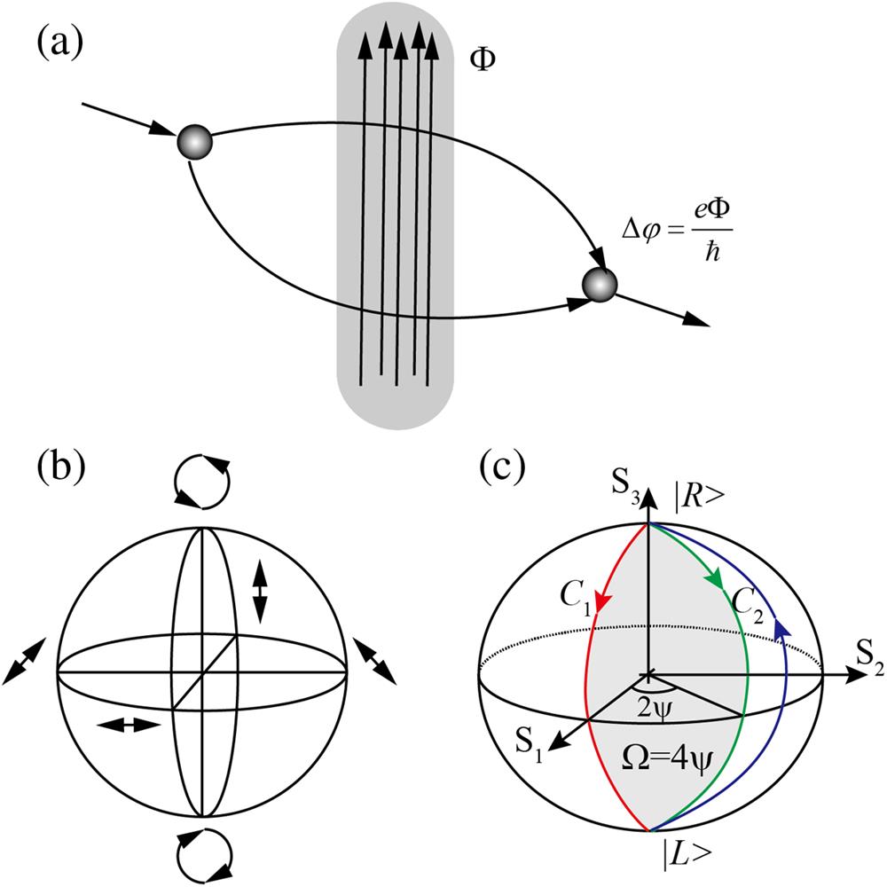
    Fig. 1. (a) Schematic illustration of AB effect, where an electron encircles a magnetic flux Φ confined to a thin, long solenoid. Although the magnetic field is zero in the vicinity of the superposed wave packets, the vector potential is non-zero outside the solenoid. Thus, the electronic wave packets acquire relative phases of exp(ieΦ/ħ), causing their interference patterns to change. (b) Polarization state representation on Poincaré sphere. (c) PB phase on Poincaré sphere, which equals half the solid angle (Ω) subtended at the origin by the area enclosed by the closed curves (C1 and C2) on the Poincaré sphere.
    Roadmap of the development of the geometric phase in optics.
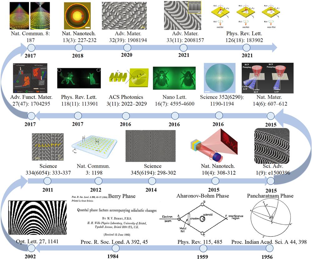
    Fig. 2. Roadmap of the development of the geometric phase in optics.
    Different elements for generating PB phase. (a) An adjustable waveguide phase shift at the microwave band is composed of a rotatable half-wave plate sandwiched between two quarter-wave plates. Reproduced with permission from Ref. [17]. (b) Actual quantized phase as a function of the desired phase, as well as discrete local grating orientation, with a scanning electron microscope (SEM) image of space-variant gratings displayed in the inset. Reproduced with permission from Ref. [25]. (c) Schematic representation of geometric phase metasurface for generating OAMs via PB phase. Reproduced with permission from Ref. [27]. (d) SEM image of geometric phase metasurface composed of space-variant plasmonic nano-apertures. Scale bar represents 500 nm. Reproduced with permission from Ref. [29].
    Fig. 3. Different elements for generating PB phase. (a) An adjustable waveguide phase shift at the microwave band is composed of a rotatable half-wave plate sandwiched between two quarter-wave plates. Reproduced with permission from Ref. [17]. (b) Actual quantized phase as a function of the desired phase, as well as discrete local grating orientation, with a scanning electron microscope (SEM) image of space-variant gratings displayed in the inset. Reproduced with permission from Ref. [25]. (c) Schematic representation of geometric phase metasurface for generating OAMs via PB phase. Reproduced with permission from Ref. [27]. (d) SEM image of geometric phase metasurface composed of space-variant plasmonic nano-apertures. Scale bar represents 500 nm. Reproduced with permission from Ref. [29].
    Quasi-continuous geometric phase. (a) SEM figure of the rotational optical catenary array and measured intensity patterns of OAMs generated through PB phase. Reproduced with permission from Ref. [30]. (b) Optical layout of wide-FOV camera with a single layer quadratic phase metalens. Optical and SEM images of fabricated wide-angle metalens composed of catenary-like structures. Reproduced with permission from Ref. [71]. (c) SEM image of cubic phase metasurface composed of catenary-like structures and measured results of the generated accelerating beams. Reproduced with permission from Ref. [73]. (d) SEM image of holographic metasurface composed of C-shaped dielectric nanoarcs and corresponding holographic images at different wavelengths. Reproduced with permission from Ref. [64].
    Fig. 4. Quasi-continuous geometric phase. (a) SEM figure of the rotational optical catenary array and measured intensity patterns of OAMs generated through PB phase. Reproduced with permission from Ref. [30]. (b) Optical layout of wide-FOV camera with a single layer quadratic phase metalens. Optical and SEM images of fabricated wide-angle metalens composed of catenary-like structures. Reproduced with permission from Ref. [71]. (c) SEM image of cubic phase metasurface composed of catenary-like structures and measured results of the generated accelerating beams. Reproduced with permission from Ref. [73]. (d) SEM image of holographic metasurface composed of C-shaped dielectric nanoarcs and corresponding holographic images at different wavelengths. Reproduced with permission from Ref. [64].
    (a) Schematic of a z-dependent polarizing device (polarizer or retarder) that enables variable polarization operations to be performed at different z planes along the optical path. (b) Measured transverse profiles of the output beam at different planes along the propagation direction for x and y incident polarizations. White arrows depict incident polarization (in the xy plane), and red arrows represent the state of polarization analyzed at each z plane. Reproduced with permission from Ref. [86]. Three-dimensional synthetic VOF generated by a monolayer composite phase metasurface: (c) schematic diagram; (d) measured intensity pattern of orthogonal linear polarizations. Black arrows depict the virtual principal axis orientation of the polarizing element at each z plane. Reproduced with permission from Ref. [89].
    Fig. 5. (a) Schematic of a z-dependent polarizing device (polarizer or retarder) that enables variable polarization operations to be performed at different z planes along the optical path. (b) Measured transverse profiles of the output beam at different planes along the propagation direction for x and y incident polarizations. White arrows depict incident polarization (in the xy plane), and red arrows represent the state of polarization analyzed at each z plane. Reproduced with permission from Ref. [86]. Three-dimensional synthetic VOF generated by a monolayer composite phase metasurface: (c) schematic diagram; (d) measured intensity pattern of orthogonal linear polarizations. Black arrows depict the virtual principal axis orientation of the polarizing element at each z plane. Reproduced with permission from Ref. [89].
    Single spin-decoupled metasurface for vectorial optical field characterization. (a) Schematic diagram. (b) Measured intensity pattern of CVVB with different intensity patterns. CVVB, cylindrical vortex vector beam. Reproduced with permission from Ref. [92].
    Fig. 6. Single spin-decoupled metasurface for vectorial optical field characterization. (a) Schematic diagram. (b) Measured intensity pattern of CVVB with different intensity patterns. CVVB, cylindrical vortex vector beam. Reproduced with permission from Ref. [92].
    Nonlinear geometric phase metasurface. (a) Nonlinear geometric phases are generated through THG of a C2 nanostructure and a C4 nanostructure. (b) Illustration of phase-controlled diffraction of THG signals for RCP light at the fundamental frequency. (c) Measured diffraction pattern of THG signals from C2 and C4 metasurfaces for circular polarization states of the fundamental and THG waves. (a)–(c) Reproduced with permission from Ref. [96]. (d) Sketch of the proposed PB nonlinear metasurface with a phase gradient in x direction. The MQW blocks are sandwiched between U-shaped gold resonators and a metallic ground plane. The incident circularly polarized wave at frequency ω generates simultaneously RCP and LCP nonlinear waves at 2ω. (e) Simulated field distributions and deflection directions of second-harmonic generation (SHG) signals of different circular polarization states. (d), (e) Reproduced with permission from Ref. [95].
    Fig. 7. Nonlinear geometric phase metasurface. (a) Nonlinear geometric phases are generated through THG of a C2 nanostructure and a C4 nanostructure. (b) Illustration of phase-controlled diffraction of THG signals for RCP light at the fundamental frequency. (c) Measured diffraction pattern of THG signals from C2 and C4 metasurfaces for circular polarization states of the fundamental and THG waves. (a)–(c) Reproduced with permission from Ref. [96]. (d) Sketch of the proposed PB nonlinear metasurface with a phase gradient in x direction. The MQW blocks are sandwiched between U-shaped gold resonators and a metallic ground plane. The incident circularly polarized wave at frequency ω generates simultaneously RCP and LCP nonlinear waves at 2ω. (e) Simulated field distributions and deflection directions of second-harmonic generation (SHG) signals of different circular polarization states. (d), (e) Reproduced with permission from Ref. [95].
    High-order linear PB phase metasurfaces. (a) Rotation dependence of the principal axis and meta-atoms with C1, C2, C3, C6, C5, and C10 rotational symmetry in the square lattice. (b) Rotation dependence of the principal axis and meta-atoms with C1, C2, C4, C8, C5, and C10 rotational symmetry in the hexagonal lattice. Double-headed arrows indicate the orientations of the principal array axis.
    Fig. 8. High-order linear PB phase metasurfaces. (a) Rotation dependence of the principal axis and meta-atoms with C1, C2, C3, C6, C5, and C10 rotational symmetry in the square lattice. (b) Rotation dependence of the principal axis and meta-atoms with C1, C2, C4, C8, C5, and C10 rotational symmetry in the hexagonal lattice. Double-headed arrows indicate the orientations of the principal array axis.
    LatticePolarizationC1C2C3C4C5C6C7C8C9C10
    SquareLCP2ϕ2ϕ6ϕ10ϕ6ϕ14ϕ18ϕ10ϕ
    RCP2ϕ2ϕ6ϕ10ϕ6ϕ14ϕ18ϕ10ϕ
    HexagonalLCP2ϕ2ϕ8ϕ20ϕ14ϕ8ϕ10ϕ
    RCP2ϕ2ϕ8ϕ20ϕ14ϕ8ϕ10ϕ
    Table 1. Geometric Phases Introduced by Meta-Atoms with C1–C10 Rotational Symmetries in the Square or Hexagonal Lattice under LCP and RCP Illuminations.
    Yinghui Guo, Mingbo Pu, Fei Zhang, Mingfeng Xu, Xiong Li, Xiaoliang Ma, Xiangang Luo. Classical and generalized geometric phase in electromagnetic metasurfaces[J]. Photonics Insights, 2022, 1(1): R03
    Download Citation