• Photonics Research
  • Vol. 8, Issue 1, 46 (2020)
Zhicheng Wu, Ming Zhou, Erfan Khoram, Boyuan Liu, and Zongfu Yu*
Author Affiliations
  • Department of Electrical and Computer Engineering, University of Wisconsin, Madison, Wisconsin 53706, USA
  • show less
    DOI: 10.1364/PRJ.8.000046 Cite this Article Set citation alerts
    Zhicheng Wu, Ming Zhou, Erfan Khoram, Boyuan Liu, Zongfu Yu. Neuromorphic metasurface[J]. Photonics Research, 2020, 8(1): 46 Copy Citation Text show less
    (a) Schematic of the neuromorphic metasurface. The neuromorphic metasurface consists of multiple layers of nanostructures, which are composed of an array of nanoribbons on top of a dielectric substrate. A handwritten digit is illuminated by a plane wave, and the scattered light then is processed by the neuromorphic metasurface. By changing the sizes of ribbons, the phase and amplitude of the transmitted light after each layer can be modified. After multiple layers, the transmitted field can be focused on specific photodetectors, which are labeled by the values of the handwritten digits, i.e., 0 to 9. (b) Intensity distribution of the transmitted light after each layer in a three-layer neuromorphic metasurface. Handwritten digits of 7 and 2 with different writing styles are used as examples. Despite the different writing styles, the transmitted light is always focused on the spot corresponding to the value of the handwritten digit. Here, we normalize the intensity of the transmitted light after each layer to its maximum for clarity.
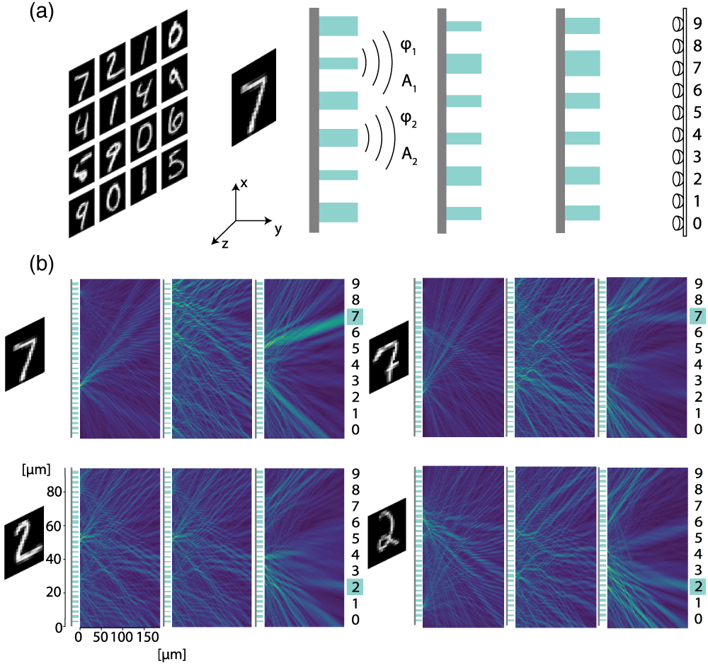
    Fig. 1. (a) Schematic of the neuromorphic metasurface. The neuromorphic metasurface consists of multiple layers of nanostructures, which are composed of an array of nanoribbons on top of a dielectric substrate. A handwritten digit is illuminated by a plane wave, and the scattered light then is processed by the neuromorphic metasurface. By changing the sizes of ribbons, the phase and amplitude of the transmitted light after each layer can be modified. After multiple layers, the transmitted field can be focused on specific photodetectors, which are labeled by the values of the handwritten digits, i.e., 0 to 9. (b) Intensity distribution of the transmitted light after each layer in a three-layer neuromorphic metasurface. Handwritten digits of 7 and 2 with different writing styles are used as examples. Despite the different writing styles, the transmitted light is always focused on the spot corresponding to the value of the handwritten digit. Here, we normalize the intensity of the transmitted light after each layer to its maximum for clarity.
    (a) Schematic of locally periodic approximation. The metasurface consists of an array of TiO2 pillars on top of a SiO2 substrate. For plane wave incidence from the bottom side of the substrate, we set up a periodic boundary condition around each pillar. The local field of the transmitted light above each pillar then is approximated by that of the corresponding periodic array. (b) The phase (blue) and amplitude (red) of transmitted light as a function of the width of the pillar under normal plane wave incidence. The results are obtained from a full-wave simulation of a periodic array of pillars, which only takes a few minutes.
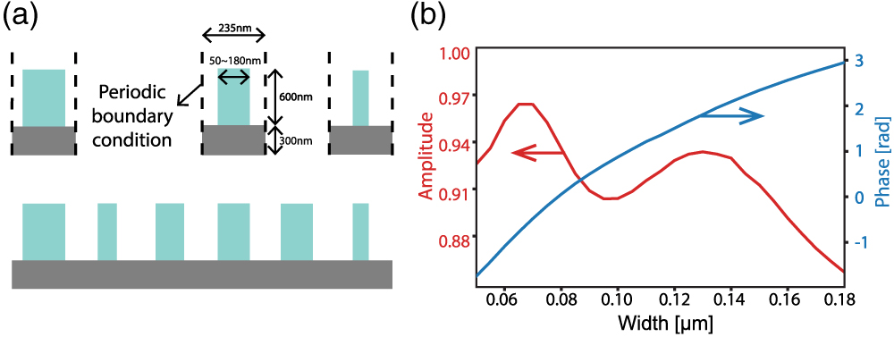
    Fig. 2. (a) Schematic of locally periodic approximation. The metasurface consists of an array of TiO2 pillars on top of a SiO2 substrate. For plane wave incidence from the bottom side of the substrate, we set up a periodic boundary condition around each pillar. The local field of the transmitted light above each pillar then is approximated by that of the corresponding periodic array. (b) The phase (blue) and amplitude (red) of transmitted light as a function of the width of the pillar under normal plane wave incidence. The results are obtained from a full-wave simulation of a periodic array of pillars, which only takes a few minutes.
    (a) Amplitude and (b) phase of the transmitted field as a function of the width of the pillar for the different incident angle α. The incident wavelength is 700 nm. When the incident angle is small, the phase response curve shifts horizontally as we increase the incident angle, while the amplitude response does not vary significantly with the incident angle. When the incident angle continues to increase, some resonances appear. The inset shows the shift of the phase response as a function of the incident angle. The shift increases nonlinearly with increasing incident angle.
    Fig. 3. (a) Amplitude and (b) phase of the transmitted field as a function of the width of the pillar for the different incident angle α. The incident wavelength is 700 nm. When the incident angle is small, the phase response curve shifts horizontally as we increase the incident angle, while the amplitude response does not vary significantly with the incident angle. When the incident angle continues to increase, some resonances appear. The inset shows the shift of the phase response as a function of the incident angle. The shift increases nonlinearly with increasing incident angle.
    (a) Forward propagation in a neuromorphic metasurface that has L layers. At the lth layer, the pillars take the far-field from the (l−1)th layer Efl−1 as input and process it. The output near-field Enl is obtained by using locally periodic approximation. The corresponding far-field Efl at the lth layer then is obtained by using near-to-far-field transformation. The final output of the neuromorphic metasurface is the intensity of light |EfL|2. (b) The training loss of a five-layer neuromorphic metasurface as a function of training steps. Each step, we use one training sample to update widths of the pillars. The training dataset is reshuffled every 50,000 steps.
    Fig. 4. (a) Forward propagation in a neuromorphic metasurface that has L layers. At the lth layer, the pillars take the far-field from the (l1)th layer Efl1 as input and process it. The output near-field Enl is obtained by using locally periodic approximation. The corresponding far-field Efl at the lth layer then is obtained by using near-to-far-field transformation. The final output of the neuromorphic metasurface is the intensity of light |EfL|2. (b) The training loss of a five-layer neuromorphic metasurface as a function of training steps. Each step, we use one training sample to update widths of the pillars. The training dataset is reshuffled every 50,000 steps.
    Comparison of light propagation (a) before and (b) after training for a five-layer neuromorphic metasurface. The input object is a handwritten digit of 2. Before training, the widths of the pillars are randomly initialized, and the transmitted light is randomly distributed at the detector. After training, the transmitted light is directed to detector 2, which corresponds to the input handwritten digit. Here, the intensity distribution of the transmitted light after each layer is also normalized by its maximum for clarity.
    Fig. 5. Comparison of light propagation (a) before and (b) after training for a five-layer neuromorphic metasurface. The input object is a handwritten digit of 2. Before training, the widths of the pillars are randomly initialized, and the transmitted light is randomly distributed at the detector. After training, the transmitted light is directed to detector 2, which corresponds to the input handwritten digit. Here, the intensity distribution of the transmitted light after each layer is also normalized by its maximum for clarity.
    Layer23456
    Accuracy80%85%88%89%90%
    Table 1. Accuracies of the Neuromorphic Metasurface for Different Number of Layers
    Zhicheng Wu, Ming Zhou, Erfan Khoram, Boyuan Liu, Zongfu Yu. Neuromorphic metasurface[J]. Photonics Research, 2020, 8(1): 46
    Download Citation