
Yifeng Yang, Yang Zhao. Opto-Mechanical System Design of Rotating Virtual Objective for Autocollimate Dynamic Target[J]. Laser & Optoelectronics Progress, 2021, 58(23): 2312003
- Laser & Optoelectronics Progress
- Vol. 58, Issue 23, 2312003 (2021)
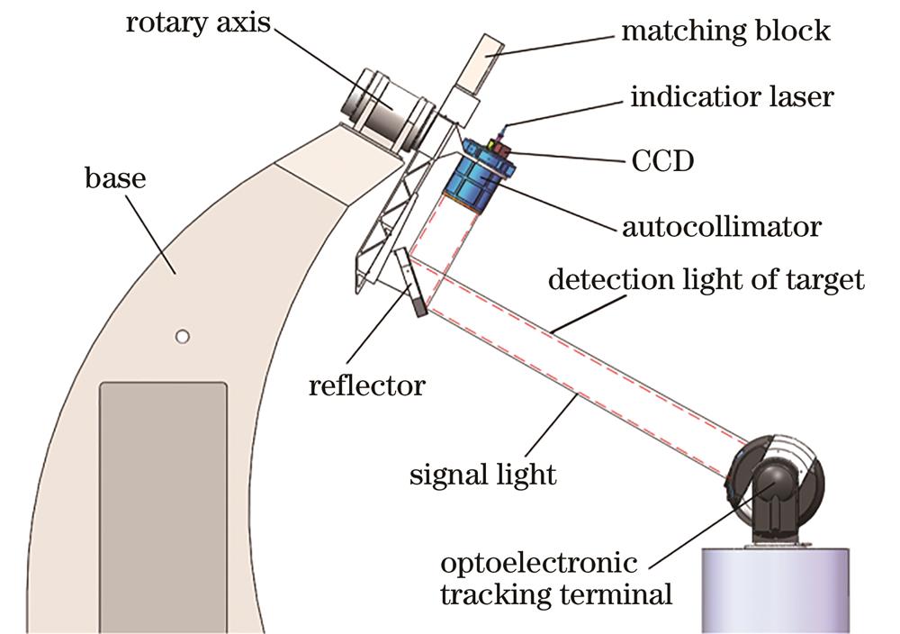
Fig. 1. Composition and detection principle of dynamic target
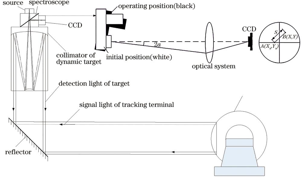
Fig. 2. Detection principle of dynamic target group
Fig. 3. Results of optical design of collimator. (a) Lightpath diagram; (b) MTF curves; (c) spot diagram
Fig. 4. Opto-mechanical structure of collimator
Fig. 5. Finite element model of main mirror and auxiliary support
Fig. 6. Relationship between RMS value of surface error and normalized radial mounting position
Fig. 7. Finite element model of collimator. (a) Finite element model; (b) finite element model with displacement constraint; (c) fundamental frequency mode
Fig. 8. Simulation results of main mirror surface shape error. (a) Finite element model; (b) rigid body displacement cloud image of main mirror; (c) surface shape error
Fig. 9. Simulation results of main mirror surface shape error at typical speed. (a) 0; (b) 60 r·min-1; (c) 100 r·min-1
Fig. 10. Relationship between main mirror surface shape error and rotational speed
Fig. 11. Detection result of wavefront difference of collimator
|
Table 1. Technical index of autocollimation dynamic target
|
Table 2. Material parameters of each component in finite element model

Set citation alerts for the article
Please enter your email address
© Copyright 2018-2021 | Chinese Laser Press. All Rights Reserved 沪ICP备15018463号-20