
Y. Y. Chu, Z. Wang, J. M. Qi, Z. P. Xu, Z. H. Li. Numerical performance assessment of double-shell targets for Z-pinch dynamic hohlraum[J]. Matter and Radiation at Extremes, 2022, 7(3): 035902
- Matter and Radiation at Extremes
- Vol. 7, Issue 3, 035902 (2022)
Abstract
I. INTRODUCTION
Z-pinches are able to create conditions for investigating extremely high-energy-density physics.1,2 The Z-pinch dynamic hohlraum (ZPDH) is an efficient scheme to construct the high-temperature radiation field required by indirect-drive inertial confinement fusion (ICF).3 Experiments on Z-pinch dynamic hohlraums have been carried out on various platforms with different current waveforms. According to experiments in the Z facility, the peak radiation temperature in a dynamic hohlraum was above 220 eV, and a deuterium–deuterium (DD) neutron yield of (1–5) × 1010 was obtained through capsule implosions radiatively driven by Z-pinch dynamic hohlraums.4 Larger-scale facilities with peak currents up to 50 MA have been proposed or are under construction with the aim of investigating ICF-related physics.5,6
Investigations of indirect-drive ICF have been boosted since the inauguration of the National Ignition Facility (NIF),7,8 where it has been demonstrated that the capsule fusion energy exceeds the energy deposited into deuterium–tritium (DT) fusion fuel in high-foot central-ignition experiments.9 The central-ignition scheme adopted in the NIF experiments requires a refined radiation temperature profile, which can be realized in a laser-driven hohlraum by precisely adjusting the injected laser power. However, the radiation temperature profile in a Z-pinch dynamic hohlraum is not so adjustable as that in a laser hohlraum. Volume ignition with double-shell capsules may well be able to adapt the radiation field of a Z-pinch dynamic hohlraum.10,11
Investigations of double-shell capsules can be traced back to the Apollo targets proposed several decades ago.12 It was generally believed that a double-shell capsule would be easily susceptible to fluid instabilities and the input energy required would be much larger than that required by central ignition.13 The YOCs (experimental fusion yields divided by one-dimensional simulated yields) in early experiments were much less than 1,14–16 and this inhibited the experimental investigation of double-shell capsules for a long time. With the development of better capsule fabrication techniques and fusion physics simulations, the YOCs approached 1, which indicated that the experimental implosion dynamics agreed well with the one-dimensional simulations.16 Now the double-shell capsule is also a complementary design for ICF investigations in laser-driven ICF.17–20
The radiation temperature profile in a Z-pinch dynamic hohlraum is very different from that in a laser-driven hohlraum. The capsule fusion yield should be optimized according to the specific radiation temperature. In reality, the radiation temperature profiles vary in different shots owing to fluctuations of driver current waveforms, and some errors may occur in the capsule fabrication. These factors will inevitably affect the fusion performance of the capsule. Besides, dynamic hohlraums are initially filled with low-opacity foam, which will change the capsule ablation dynamics and the capsule performance. We will discuss these problems in this paper.
The remainder of this paper is organized as follows. The dynamics of a double-shell capsule are investigated in Sec. II. Factors that influence capsule behavior are discussed in Sec. III. Finally, a summary is given in Sec. IV.
II. DYNAMICS OF DOUBLE-SHELL CAPSULE
A. Estimation of radiation temperature
The dynamic hohlraum (DH) is an efficient scheme for converting Z-pinch kinetic energy to radiative energy. Z-pinch magnetic and dynamic hohlraum experiments have been carried out in different-scale facilities with peak currents ranging from 1 to 20 MA. The scaling law of dynamic-hohlraum radiation temperature vs peak drive current can be approximated well as
A Z-pinch driver with a peak current greater than 50 MA is believed to be able to generate an extremely high-energy-density plasma and to produce a considerable number of fusion neutrons. Russian scientists proposed the Baikal project to build a 50 MA Z-pinch facility,5 and American scientists proposed two conceptual facilities, Z300 (nearly 50 MA) and Z800 (nearly 70 MA), for investigation of Z-pinch driven fusion.6 Based on the scaling law, the peak radiation temperature reaches 339 eV when the peak driver current is 50 MA, and it reaches 368 eV when the peak driver current is 60 MA. When additional objects are present in a dynamic hohlraum, such as a fusion capsule, the peak temperature of the hohlraum will be depressed. In the following simulation, we take a Gaussian waveform for the radiation temperature profile:
B. Capsule structures
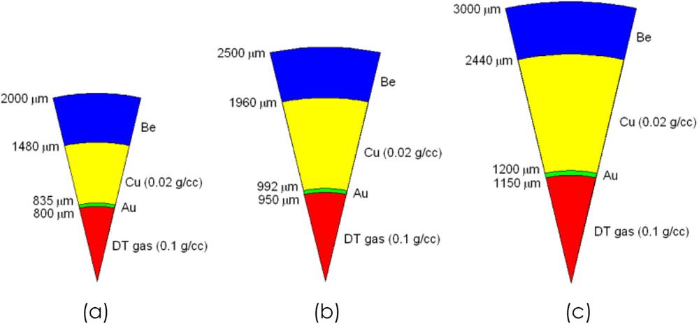
A double-shell capsule consists of four main parts, namely, an ablator layer, a cushion layer, a pusher layer, and the DT fuel.17,18 In this paper, the material of the ablator layer is solid beryllium, that of the cushion layer is copper foam with density 20 mg/cm3, that of the pusher layer is solid gold, and the DT fuel is room-temperature high-pressure equimolar DT gas with density 100 mg/cm3.
Capsules with three different outer radii are displayed in Fig. 1, and their main features are listed in Table I. The implosion and fusion process of the double-shell capsule is simulated with the one-dimensional Lagrangian radiation hydrodynamic code MULTI-IFE.22 The electron and ion temperatures are considered separately, and the radiation is treated using the multigroup radiation transport method. The capsules are driven to implode by thermal radiation with a profile given by Eq. (1). The radiation temperature profile is applied as a boundary condition at the outer radius of the capsule ablator. The equations of state for the plasmas are obtained from the QEOS model,23 and the radiation-related parameters are obtained from the averaged-atom model.24 Thirty radiation groups, ranging from 1eV to 20 keV, are used in the simulation. The fusion neutrons are released freely in the simulation, and the energy transport of the fusion α particles is treated using a diffusion model. With increasing capsule radius, the fusion energy yields increase from 28.8 to 101.6 MJ. The influence of the implosion capsule on the dynamic hohlraum is not taken into account here, since this influence is of little importance when the capsule is sufficiently small compared with the dynamic hohlraum. When the size of the dynamic hohlraum is not large enough, the symmetry of the radiation field felt by the smaller capsule can be much greater than that felt by the larger capsule. In the following, we will take the capsule with radius 2.5 mm as an example to illustrate the capsule implosion performance.
![]()
Figure 1.Schematics of capsules with different radii: (a) 2 mm; (b) 2.5 mm; (c) 3 mm.
| Capsule label | I | II | III |
|---|---|---|---|
| Capsule radius (mm) | 2 | 2.5 | 3 |
| Ablator mass (mg) | 36.673 | 62.395 | 96.136 |
| Cushion mass (mg) | 0.223 | 0.549 | 1.072 |
| Pusher mass (mg) | 5.68 | 9.616 | 16.762 |
| Fuel mass (mg) | 0.215 | 0.359 | 0.637 |
| Fusion energy (MJ) | 28.8 | 56.1 | 101.6 |
| Burn efficiency | 0.40 | 0.46 | 0.47 |
Table 1. Main features of the three double-shell capsules.
C. Implosion dynamics
Figure 2 shows the calculated flow plot and fusion power for the 2.5 mm-radius double-shell capsule. The ablation layer collides with the pusher layer at 25 ns, which is about 5 ns later than the peak time of the driven radiation. The fuel is compressed to its densest state at about 30.07 ns, and this time will henceforth be referred as the stagnation time. The fusion power waveform indicates that the most intense fusion reaction takes place at about 30.22 ns, which is slightly later than the stagnation time. The FWHM of the fusion power is about 0.1 ns, and the total fusion energy is 56.1 MJ. For a 50 MA Z-pinch driver that is able to generate a 300 eV dynamic hohlraum, the initial energy storage in the facility is typically 50 MJ. The initial energy storage for the conceptual Z300 facility is 48 MJ,6 and that for the Baikal facility is about 60 MJ.5 Energy breakeven can be achieved by imploding a double-shell capsule in a 50 MA Z-pinch dynamic hohlraum, if a high-temperature and high-symmetry radiation field can be well established in the hohlraum. Control of radiation symmetry is of great importance for spherical implosion of the fusion capsule, and the symmetry can be improved by placing radiation burn-through shields in the dynamic hohlraum.25 Besides, when radiation asymmetry is present, spherical fuel compression can also be achieved by adopting nonspherical or variable-thickness ablators, and this needs more detailed information about the radiation temperature distribution and sophisticated multidimensional radiation hydrodynamics simulations.
![]()
Figure 2.(a) Implosion flow plot with scaled radiation temperature profile and scaled fusion power. (b) Flow plot near stagnation. (c) Fusion power waveform. The driven radiation temperature profile
Efficient energy coupling between different layers is crucial for the fusion process. If the layer properties are mismatched, then the pusher cannot gain enough kinetic energy, and the DT fuel cannot be compressed to the high-energy-density state required for self-sustaining nuclear fusion. The evolutions of the kinetic and total energy before stagnation are displayed in Fig. 3 for all four layers. The evolution of the kinetic energy reflects the movement of each layer. From 15 ns on, the ablator clearly begins to be ablated. At 20.5 ns, the cushion layer begins to be compressed inward. At 25 ns, the pusher layer begins to gain kinetic energy rapidly by colliding with the imploding ablator and cushion layer. The maximum kinetic energy gained by the whole ablator is about 1.15 MJ. The cushion layer has little mass compared with the ablator, and so the kinetic energy carried by the cushion layer can be neglected in comparison with that carried by the ablator. The maximum kinetic energy of the pusher is 174 kJ, and the corresponding mean implosion velocity
![]()
Figure 3.Evolutions of (a) kinetic energies and (b) total energies of different layers. The total energy is the sum of the internal energy and kinetic energy.
D. Ignition analysis
Ignition conditions are different for central ignition and volume ignition. Central ignition requires an extremely hotspot surrounded by the cold dense DT fuel. The ion temperature of the hotspot needs to reach about 10 keV. Volume ignition usually requires a lower ion temperature than central ignition.18 When self-sustaining nuclear fusion is achieved, the ion temperature varies sharply around ignition time. We shall first determine the ignition time. For the central DT fuel, the rate of change of the internal energy can be expressed as follows:26
![]()
Figure 4.Power analysis for the DT fuel region (a) over a long time span and (b) near the ignition time, and (c) time-integrated power curve. The surface power loss is defined as the sum of all the conductive power losses, namely, the radiative loss, electronic conductive loss, and ionic conductive loss. Negative work loss indicates fuel heating, and positive work loss indicates fuel cooling.
Fuel density and ion temperature are crucial for plasma ignition and burning. According to the simulated results in Fig. 5, the fuel radius is about 0.12 mm when ignition occurs (29.84 ns), and the corresponding mean density is about 44 g/cm3. The areal density of the DT fuel, ρR, is about 0.53 g/cm2, which is large enough to deposit the fusion α particles effectively. The central ion temperature is about 4.5 keV, which is much lower than the hot-spot temperature required for typical central ignition. The ignition fuel is near isotonic, and the central pressure is only slightly larger than the outer pressure. The mean ignition pressure is about 80 Gbar, which is also lower than the hot-spot pressure required by central ignition. The hot-spot pressure of the point design capsule for the NIF is over 300 Gbar.27 When turning offthe fusion reaction, the ion temperature and density of the central fuel at stagnation time are about 3.5 keV and 82g/cm3, respectively. The less extreme conditions here may relax the requirement for compression symmetry.
![]()
Figure 5.Radial distributions of fuel densities, pressures, and ion temperatures at five different times around ignition.
E. Compression of double-shell capsule inside Z-pinch dynamic hohlraum
When the double-shell capsule lies in a Z-pinch dynamic hohlraum (ZPDH), the coupling between the capsule and the hohlraum is of key importance to fusion performance. Here, we will give a direct illustration of the capsule implosion inside the ZPDH. The double-shell capsule has the structural parameters shown in Fig. 1(b). The ZPDH load structure and the drive current profile are shown in Fig. 6. The linear mass of the Z-pinch tungsten shell is 22.6 mg/cm, the density of the prefilled dilute tungsten plasma is 0.05 mg/cm3, and the density of the CHO radiation converter is 20 mg/cm3. The prefilled dilute tungsten plasma is introduced to make the problem-solving area continuous, and its density here is low enough that it will not have any significant effect on the implosion dynamics of the main plasma shell. The dynamical process of the ZPDH load is simulated with the upgraded MULTI2D, which is a two-dimensional Lagrangian radiative magnetic hydrodynamic (RMHD) code.28–30 In the calculation, no initial perturbations are imposed, and the plasmas shell implodes nearly synchronously before collision with the radiation converter. This indicates that numerical instability is controlled well in the simulation. If initial perturbations were imposed, the plasma shell would be significantly distorted, and the equivalent density of the main plasma shell would be reduced. The impact between the plasma shell and the radiation converter would be weakened. A high-temperature dynamic hohlraum begins to be established after the impact of the plasma shell with the radiation converter, and the double-shell capsule inside is ablated and driven to implode.
![]()
Figure 6.Cross-sectional schematic of the ZPDH load (left), and the input drive current profile (right).
The plasma density distributions at two different times for the ZPDH load are shown in Fig. 7. The high-temperature radiation field at large radius is established a little earlier than that near the axis, and so the waist of the ablator (around z = 0) begins to be ablated and impacts with the pusher a little earlier. The initial radius of the fuel is 0.95 mm. When the mean radius of the fuel is compressed to be about 0.5 mm (at 393.3 ns), the fuel–pusher interface deviates slightly from a spherical shape. When the mean radius of the fuel is compressed to be about 0.2 mm (at 394.5 ns), the fuel–pusher interface retains its spherical shape well, except for a small region in the equatorial direction (around z = 0). This indicates that the near-spherical implosion of the double-shell capsule can be preserved, and the one-dimensional simulation works well. The radiation temperature profiles at two different positions on the capsule surface are shown in Fig. 8. The equatorial and polar radiation temperature profiles agree well with each other. The radiation temperature profile increases sharply at about 384 ns, and the radiation temperature reaches nearly 300 eV at 386 ns. Then, the radiation temperature remains above 300 eV before the capsule fuel stagnates (at about 395 ns). Because the radiation temperature profile here can drive the capsule to implode more powerfully, the capsule implosion time here is about 10 ns, which is shorter than that shown in Fig. 2 (about 15 ns). For greater implosion symmetry, the radiation field felt by the capsule can be smoothed by placing appropriate radiation shields in the radiation converter. This will need much more detailed two-dimensional simulations and optimizations, which will be performed in our future work.
![]()
Figure 7.Density distributions of the ZPDH plasma at 393.3 and 394.5 ns. In the enlarged panels, the black solid line indicates the fuel–pusher interface, and the blue dashed circle indicates a sphere of the same radius.
![]()
Figure 8.Radiation temperature profiles at two different positions on the capsule surface. The red solid line indicates the equatorial radiation temperature profile, and the blue dotted line indicates the polar radiation temperature profile.
III. FACTORS INFLUENCING FUSION YIELD
Many factors influence the performance of a double-shell capsule. The hohlraum temperature profile will be different from the assumed Gaussian waveform. Capsule fabrication may introduce some uncertainties about the structural parameters. The boundary of a dynamic hohlraum with finite-density filling can alter the ablation process by limiting the expansion of the ablator material. In this section, we will investigate the influence of these factors.
A. Radiation temperature profile
In indirect-drive ICF, the fusion capsule should be consistent with the radiation temperature profile. The radiation profile is especially important for central ignition, and this has been confirmed by investigations of laser-driven ICF at the NIF.31–33 It is believed that the fusion performance of a double-shell capsule is not so sensitive to the radiation temperature profile as that of a single-shell central-ignition capsule. A Gaussian radiation temperature profile is characterized mainly by two parameters, namely, the peak temperature and the FWHM. Fusion energy yields with the 2.5 mm-radius double-shell capsule [shown in Fig. 1(b)] driven by different radiation temperature profiles are displayed in Fig. 9. For the radiation temperature profile with a width of 10 ns, the fusion yield remains above 50 MJ when the peak radiation temperature ranges from 290 to 320 eV. For the radiation temperature profile with a peak temperature of 300 eV, the fusion yield exceeds 50 MJ when the width is larger than 9 ns. When the width is less than 7 ns, the fusion yield is very small, whatever value the peak temperature takes between 270 and 350 eV. This indicates that the capsule does not match the excessively narrow radiation temperature profile, and the capsule parameters should be modified appropriately. Table II shows the maximum energy absorbed by the capsule, the maximum kinetic energy of the pusher layer, and the maximum internal energy of the DT fuel when the driven radiation temperature profile is changed. The maximum internal energy of the fuel is crucial for fuel ignition, and the capsule fails to ignite when Ei,fuel is below 80 kJ. With the FWHM of the radiation profile kept at 10 ns, Eabs,capsule increases with increasing peak temperature, but Ei,fuel (kJ) decreases when the peak temperature is too high (
![]()
Figure 9.Influence of the radiation temperature profile characteristics on the fusion energy yields (in MJ) with the 2.5 mm-radius double-shell capsule.
| Peak (eV) | FWHM (ns) | Eabs,capsule (MJ) | Ek,pusher (kJ) | Ei,fuel (kJ) |
|---|---|---|---|---|
| 280 | 10 | 1.63 | 112.8 | 65.3 |
| 300 | 10 | 2.06 | 173.8 | 91.3 |
| 320 | 10 | 2.49 | 171.7 | 90.0 |
| 340 | 10 | 2.82 | 158.5 | 86.3 |
| 300 | 12 | 2.32 | 201.8 | 103.2 |
| 300 | 8 | 1.72 | 124.9 | 70.7 |
Table 2. Maximum energy absorbed by the capsule Eabs,capsule, maximum kinetic energy of the pusher layer Ek,pusher, and maximum internal energy of the DT fuel Ei,fuel for different peak values or different FWHM of the driven radiation temperature profile with a Gaussian shape. In the calculation, the fusion process is switched off.
For a Z-pinch dynamic hohlraum, the hohlraum will be preheated owing to collision with the imploded precursor plasma or by irradiation of the main plasma shell, and a foot pulse may be present in the radiation temperature profile. The radiation temperature profile (in eV) with a foot pulse is here expressed with a uplifted Gaussian waveform
B. Capsule parameter variation
Some uncertainties are unavoidable in nonideal capsule fabrication. For example, the DT gas pressure (or density) or the cushion foam density may deviate from the designed value. The thickness of each layer may also be different from the designed one. Asymmetry and nonconcentricity of the capsule can lead to nonspherical implosions, although these will not be covered in the current study. Figure 10(a) shows the sensitivity of the fusion yield to the ablator thickness. When the ablator thickness ranges from 500 to 630 µm, the fusion yield remains above 50 MJ. Figure 10(b) shows the sensitivity of the fusion yield to the pusher thickness. When the pusher thickness ranges from 31 to 55 µm, the fusion yield remains above 50 MJ. Figure 10(c) shows the sensitivity of the fusion yield to the fuel density. The fusion yield increases almost linearly as the fuel density increases from 0 to 0.1 g/cm3, and the fusion yield reaches a peak value 59.0 MJ when the fuel density is about 0.11 g/cm3. Figure 10(d) shows the sensitivity of the fusion yield to the cushion foam density. The fusion yield begins to decrease sharply only when the foam density exceeds about 0.1 g/cm3. Based on the sensitivity analysis here, the 2.5 mm-radius double-shell capsule can gain a stable fusion energy yield when the capsule parameters lie in a quite wide span. Table III shows the maximum energy absorbed by the capsule, the maximum kinetic energy of the pusher layer, and the maximum internal energy of the DT fuel when the capsule parameters are changed. By changing the parameters of the ablator, the pusher, and the cushion layers, the maximum internal energy of the fuel can be changed. The capsule fails to ignite when Ei,fuel is less than 86 kJ.
![]()
Figure 10.Sensitivities of fusion energy yield to (a) ablator thickness, (b) pusher thickness, (c) fuel density, and (d) cushion density.
| Changed property | Value | Eabs,capsule (MJ) | Ek,pusher (kJ) | Ei,fuel (kJ) |
|---|---|---|---|---|
| Ablator thickness | 400 μm | 1.73 | 121.2 | 66.8 |
| 500 μm | 1.99 | 171.7 | 90.1 | |
| 600 μm | 2.17 | 156.9 | 86.4 | |
| 700 μm | 2.35 | 132.8 | 74.8 | |
| Pusher thickness | 10 μm | 2.01 | 72.9 | 85.3 |
| 30 μm | 2.04 | 153.9 | 98.2 | |
| 50 μm | 2.07 | 181.8 | 86.6 | |
| 70 μm | 2.11 | 186.9 | 65.3 | |
| Fuel density | 0.05 g/cm3 | 2.06 | 184.8 | 61.4 |
| 0.10 g/cm3 | 2.06 | 173.8 | 91.3 | |
| 0.15 g/cm3 | 2.06 | 165.1 | 113.9 | |
| 0.20 g/cm3 | 2.06 | 157.7 | 128.9 | |
| Cushion density | 0.05 g/cm3 | 2.06 | 175.1 | 92.3 |
| 0.10 g/cm3 | 2.06 | 168.0 | 86.7 | |
| 0.15 g/cm3 | 2.07 | 157.8 | 80.2 | |
| 0.20 g/cm3 | 2.07 | 149.7 | 76.6 |
Table 3. Maximum energy absorbed by the capsule Eabs,capsule, maximum kinetic energy of the pusher layer Ek,pusher, and maximum internal energy of the DT fuel Ei,fuel when the capsule parameters deviate from those shown in
C. Boundary effect
A Z-pinch dynamic hohlraum is initially filled with a low-density foam with quite low opacity, such as a hydrocarbon. The foam density in a dynamic hohlraum can approach 10 mg/cm3, while the density of the filled medium in the hohlraum is only about 1 mg/cm3 for indirect-drive laser ICF.34 With shrinkage of the dynamic hohlraum and under compression by the expanded ablator, the foam density in the dynamic hohlraum will be increased. Here, we conceive a five-layer capsule to investigate the influence of the dynamic hohlraum converter foam. The inner four layers are the same as those of the previous double-shell capsule shown in Fig. 1(b), and the outermost layer is set to be of thickness 0.5 mm and of CH material to mimic the scenario in the dynamic hohlraum. The drive radiation temperature is exerted on the outer surface of the CH layer. A rigid boundary condition is imposed at outer boundary. Figure 11 shows a simulated implosion flow plot of the double-shell capsule surrounded by CH foam with density 50 mg/cm3. The peak fusion power is located at about 30.40 ns, and that in Fig. 2(c) is about 30.21 ns. The released fusion energy is 56.5 MJ and very close to the simulated fusion yield in Fig. 2. This indicates that the fuel compression status is not altered drastically.
![]()
Figure 11.(a) Implosion flow plot of the double-shell capsule surrounded by CH foam with density 50 mg/cm3. (b) Corresponding fusion power released.
IV. SUMMARY
The Z-pinch dynamic hohlraum is an efficient scheme to establish a high-temperature radiation field, which can be applied to indirect drive ICF. According to a scaling law based on the existing experimental data, the peak radiation temperature in a dynamic hohlraum can exceed 300 eV when the Z-pinch driver peak current reaches 50 MA. Volume ignition with a room-temperature double-shell capsule, as an additional option in laser-driven ICF, may be feasible in ICF indirectly driven by a Z-pinch dynamic hohlraum.
In this paper, the performances of double-shell capsules have been numerically investigated in the radiation environment of a Z-pinch-driven dynamic hohlraum. Under irradiation by a 300 eV radiation field, optimized capsules with radii of 2, 2.5, and 3 mm are able to generate fusion energy yields of 28.8, 56.1, and 101.6 MJ respectively, according to a one-dimensional calculation. In the case of ignition with the 2.5 mm-radius capsule, the areal density is about 0.53 g/cm2, the pressure is about 80 Gbar, and the central ion temperature is about 4.5 keV. According to a two-dimensional simulation, near-spherical compression of the fusion fuel can be achieved when the double-shell capsule is radiatively driven by the Z-pinch dynamic hohlraum. The fusion energy yields from the one-dimensional simulation are quite stable when the radiation pulse changes over a wide range or has a high–foot profile. The sensitivities of the fusion energy yield to the capsule parameters have been investigated through a one-dimensional simulation to illustrate the influence of the capsule fabrication biases. The implosion of the double-shell capsule embedded in low-density CH foam has been simulated to mimic the influence of the finite-density dynamic hohlraum on the implosion of the interior capsule. The presence of 50 mg/cm3 foam does not change the fusion yield greatly.
In general, a double-shell capsule can generate a considerable fusion yield, and the capsule performance is stable against moderate variations of the driving conditions or the structural parameters. The present investigation has been mostly restricted to one-dimensional simulations, and the effects beyond spherical implosion have not been taken into account here. Some nonideal effects, such as driver asymmetry, capsule nonconcentricity, and interface instabilities, are of great importance for the capsule implosion, and these need to be further investigated in the future work. Real inertial fusion systems have many complex engineering details, such as the hemispherical structure of the capsule pusher layer35 and the fuel filling tube of the capsule. These structural details can lead to mixing of high-Z materials into the fusion fuel, which can greatly increase fuel radiation losses. The fusion performances of the capsules designed here may be influenced by these nonideal structures, and future detailed two-dimensional simulations will be used to estimate the sensitivity of the fusion performance to structural details and pusher–fuel mixing.
ACKNOWLEDGMENTS
Acknowledgment. We would like to thank Dr. Rafael Ramis and Dr. Fuyuan Wu for their assistance with using the MULTI codes. This work has been carried out within the framework of conceptual design of the Z-FFR (Z-Pinch Driven Fusion–Fission Hybrid Reactor) and supported by the National Natural Science Foundation of China (Grant No. 11875239).
References
[1] M. K.Matzen. Z pinches as intense x-ray sources for high-energy density physics applications. Phys. Plasmas, 4, 1519(1997).
[2] M. G.Haines. A review of the dense Z-pinch. Plasma Phys. Controlled Fusion, 53, 093001(2011).
[3] T. W. L.Sanford et al.
[4] C. L.Ruiz et al. Production of thermonuclear neutrons from deuterium-filled capsule implosions driven by Z-pinch dynamic hohlraums. Phys. Rev. Lett., 93, 015001(2004).
[5] E. V.Grabovski et al(2013).
[6] W. A.Stygar et al. Conceptual designs of two petawatt-class pulsed-power accelerators for high-energy-density-physics experiments. Phys. Rev. Spec. Top.–Accel. Beams, 18, 110401(2015).
[7] N. B.Meezan et al. Indirect drive ignition at the National Ignition Facility. Plasma Phys. Controlled Fusion, 59, 014021(2017).
[8] R.Betti et al. Inertial-confinement fusion with lasers. Nat. Phys., 12, 435(2016).
[9] O. A.Hurricane et al. Fuel gain exceeding unity in an inertially confined fusion implosion. Nature, 506, 343(2016).
[10] T. A.Mehlhorn et al. Recent experimental results on ICF target implosions by Z-pinch radiation sources and their relevance to ICF ignition studies. Plasma Phys. Controlled Fusion, 45, A325(2003).
[11] C.Mao et al. Analytical physical models for cryogenic double-shell capsule design driven by Z-pinch dynamic
[12] J.Lindl. Development of the indirect-drive approach to inertial confinement fusion and the target physics basis for ignition and gain. Phys. Plasmas, 2, 3933(1995).
[13] J. D.Lindl. Inertial Confinement Fusion(1998).
[14] E. M.Campbell et al. Nova experiments facility (invited). Rev. Sci. Instrum., 57, 2101(1986).
[15] T. R.Boehly et al. Initial performance results of the OMEGA laser system. Opt. Commun., 133, 495(1997).
[16] W. S.Varnum et al. Progress toward ignition with noncryogenic double-shell capsules. Phys. Rev. Lett., 84, 5153(2000).
[17] P.Amendt et al. Indirect-drive noncryogenic double-shell ignition targets for the National Ignition Facility: Design and analysis. Phys. Plasmas, 9, 2221(2002).
[18] P.Amendt et al. An indirect-drive non-cryogenic double-shell path to 1
[19] D. S.Montgomery et al. Design considerations for indirectly driven double shell capsules. Phys. Plasmas, 25, 092706(2018).
[20] D. C.Wilson et al. Single and double shell ignition targets for the National Ignition Facility at 527 nm. Phys. Plasmas, 28, 052704(2021).
[21] T. J.Nash et al. High-temperature dynamic hohlraums on the pulsed power driver
[22] R.Ramis et al. MULTI-IFE—A one-dimensional computer code for Inertial Fusion Energy (IFE) target simulations. Comput. Phys. Commun., 203, 226(2016).
[23] R. M.More et al. A new quotidian equation of state (QEOS) for hot dense matter. Phys. Fluids, 31, 3059(1988).
[24] G. D.Tsakiris et al. An approximate method for calculating Planck and Rosseland mean opacities in hot, dense plasmas. J. Quant. Spectrosc. Radiat. Transfer, 38, 353(1987).
[25] S. A.Slutz et al. Dynamic hohlraum driven inertial fusion capsules. Phys. Plasmas, 10, 1875(2003).
[26] S.Atzeni, J.Meyer-ter-Vehn. The Physics of Inertial Fusion(2004).
[27] J.Lindl et al. Review of the National Ignition Campaign 2009-2012. Phys. Plasmas, 21, 020501(2014).
[28] R.Ramis et al. MULTI2D—A computer code for two-dimensional radiation hydrodynamics. Comput. Phys. Commun., 180, 977(2009).
[29] F.Wu et al. A conservative MHD scheme on unstructured Lagrangian grids for Z-pinch hydrodynamic simulations. J. Comput. Phys., 357, 206(2018).
[30] F.Wu et al. Numerical studies on the radiation uniformity of Z-pinch dynamic hohlraum. Matter Radiat. Extremes, 3, 248(2018).
[31] T. R.Dittrich et al. Design of a high-foot high-adiabat ICF capsule for the National Ignition Facility. Phys. Rev. Lett., 112, 055002(2014).
[32] D. T.Casey et al. Improved performance of high areal density indirect drive implosions at the National Ignition Facility using a four-shock adiabat shaped drive. Phys. Rev. Lett., 115, 105001(2015).
[33] L. F.Wang et al. A scheme for reducing deceleration-phase Rayleigh–Taylor growth in inertial confinement fusion implosions. Phys. Plasmas, 23, 052713(2016).
[34] D. E.Hinkel et al. Development of improved radiation drive environment for high foot implosions at the National Ignition Facility. Phys. Rev. Lett., 117, 225002(2016).
[35] D. J.Stark et al. Detrimental effects and mitigation of the joint feature in double shell implosion simulations. Phys. Plasmas, 28, 052703(2021).


Set citation alerts for the article
Please enter your email address

© Copyright 2018-2021 | Chinese Laser Press. All Rights Reserved 沪ICP备15018463号-20