
Zhongguo Guo, Guanfeng Guo, Zhongkun Li, Yongming Zhong, Changsheng Zeng, Yishi Han. Microwave Phase-Shifting Signal Generation with Adjustable Frequency-Multiplication Factor Based on Polarization Division Multiplexing Dual-Parallel Mach-Zehnder Modulator[J]. Laser & Optoelectronics Progress, 2022, 59(13): 1307002
- Laser & Optoelectronics Progress
- Vol. 59, Issue 13, 1307002 (2022)
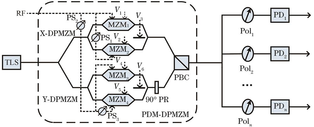
Fig. 1. Structure diagram of microwave phase-shifting signal generation scheme with adjustable frequency-multiplication factor
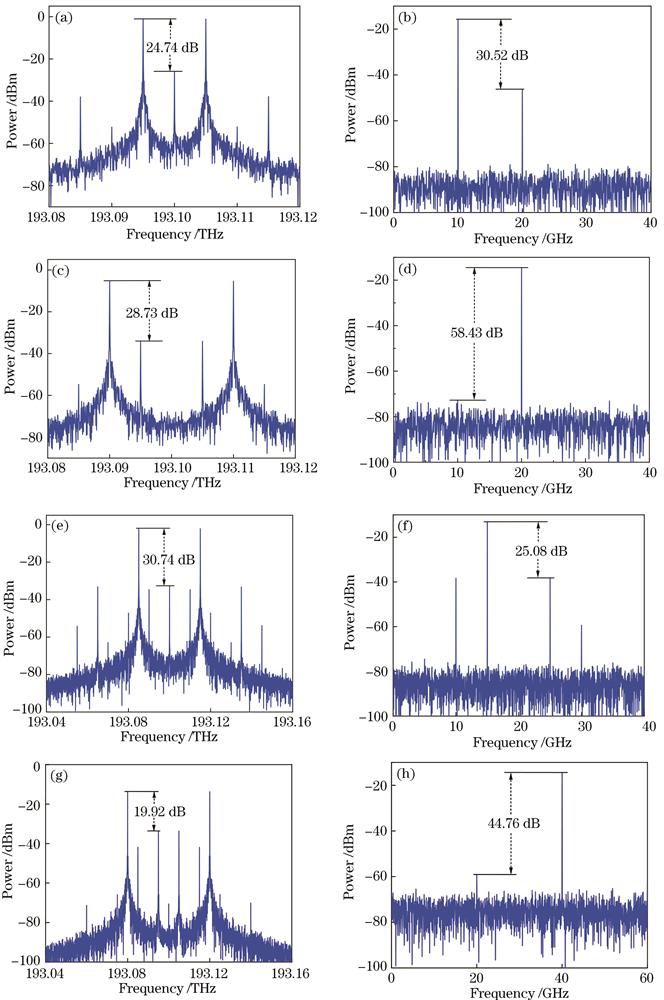
Fig. 2. Output optical spectra of PDM-DPMZM and output electrical spectra of PD. (a),(c),(e),(g) Output optical spectra when FMF is 2, 4, 6, 8 respectively; (b),(d),(f),(h) output electrical spectra when FMF is 2, 4, 6, 8 respectively
Fig. 3. Waveforms of microwave phase-shifting signals. (a) Frequency-doubled; (b) frequency-quadrupled; (c) frequency-sextupled; (d) frequency-octupled
Fig. 4. Relationship between phase of generated signal and α
Fig. 5. Microwave phase-shifting signals of different frequencies. (a) Phase response; (b) power response
Fig. 6. Relationship among ESSR, output electrical power, and extinction ratio. (a) ESSR; (b) output electrical power
Fig. 7. Influence of DC bias voltage drift on ESSR and output electrical power. (a) ESSR; (b) output electrical power
Fig. 8. Influence of amplitude and phase imbalance of electrical phase shifter on phase drift and power fluctuation. (a),(c) Influence of amplitude and phase imbalance on phase drift; (b),(d) influence of amplitude and phase imbalance on power fluctuation

Set citation alerts for the article
Please enter your email address
© Copyright 2018-2021 | Chinese Laser Press. All Rights Reserved 沪ICP备15018463号-20