
Oskars Ozolins, Vjaceslavs Bobrovs. Theoretical study of all-optical RZ-OOK to NRZ-OOK format conversion in uniform FBG for mixed line-rate DWDM systems[J]. Chinese Optics Letters, 2015, 13(6): 060603
- Chinese Optics Letters
- Vol. 13, Issue 6, 060603 (2015)
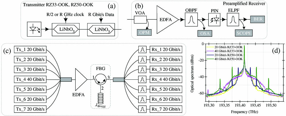
Fig. 1. Setup for modulation format conversion: (a) RZ–OOK transmitter; (b) optical receiver; (c) system configuration; (d) 20 and 40 Gbit/s 33% and 50% duty cycle RZ–OOK spectra.
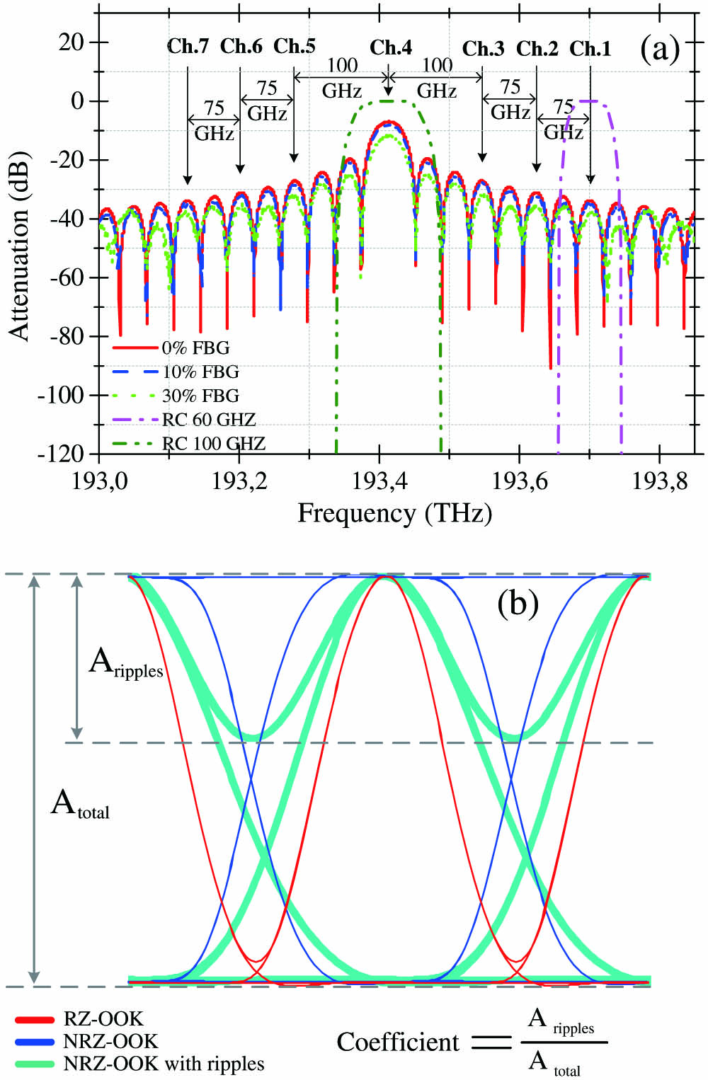
Fig. 2. (a) Uniform FBG and RC filters amplitude transfer functions used in the setup; (b) “1” level amplitude ripples evaluation with coefficient.
Fig. 3. Optical spectra for (a) RZ33–OOK and (b) RZ50–OOK in MLR DWDM system (resolution bandwidth, 0.01 nm).
Fig. 4. BER as a function of received power: (a) RZ33–OOK and (f) RZ50–OOK to NRZ–OOK modulation format conversion with different uniform FBG filters for fourth channel in MLR DWDM system. Insets, eye diagrams of B2B; (b) RZ33–OOK and (g) RZ50–OOK signals and converted NRZ–OOK signals after modulation format converters with (c) and (h) 0%, (d) and (i) 10%, and (e) and (j) 30% amplitude noise in uniform contrast profile.
Fig. 5. BER as a function of received power: (a) RZ33–OOK and (f) RZ50–OOK to NRZ–OOK modulation format conversion with different uniform FBG filters for first channel in MLR DWDM system. Insets, eye diagrams of B2B; (b) RZ33–OOK and (g) RZ50–OOK signals and converted NRZ–OOK signals after modulation format converters with (c) and (h) 0%, (d) and (i) 10%, and (e) and (j) 30% amplitude noise in uniform contrast profile.
Fig. 6. (a) Power penalty for MLR RZ33–OOK DWDM system and eye diagrams for converted 20 Gbit/s NRZ–OOK after modulation format converters with (b) 0%, (c) 10%, and (d) 30% amplitude noise in uniform contrast profile and 40 Gbit/s NRZ–OOK after modulation format converters with (e) 0%, (f) 10%, and (g) 30% amplitude noise in uniform contrast profile.
Fig. 7. (a) Power penalty for MLR RZ50–OOK DWDM system and eye diagrams for converted 20 Gbit/s NRZ–OOK after modulation format converters with (b) 0%, (c) 10%, and (d) 30% amplitude noise in uniform contrast profile and 40 Gbit/s NRZ–OOK after modulation format converters with (e) 0%, (f) 10%, and (g) 30% amplitude noise in uniform contrast profile.
Fig. 8. Q
Fig. 9. Coefficient as a function of offset between uniform FBG central wavelength and channel central wavelength for (a) 40 and (b) 20 Gbit/s RZ–OOK to NRZ–OOK modulation format conversion in MLR DWDM system.

Set citation alerts for the article
Please enter your email address
© Copyright 2018-2021 | Chinese Laser Press. All Rights Reserved 沪ICP备15018463号-20