Abstract
In this work we study all-optical multi-channel return-to-zero (RZ)–on-off keying (OOK) to nonreturn-to-zero (NRZ)–OOK format conversion in single uniform fiber Bragg grating (FBG) for mixed line-rate dense wavelength-division multiplexing systems using mathematical simulations. Forty and 20 Gbit/s RZ–OOK signals with 33% and 50% duty cycles are converted to NRZ–OOK signals in single uniform FBG with 21% reflectivity. Impact of amplitude noise from FBG contrast profile on modulation format conversion efficiency is also studied.Fiber optic transmission systems (FOTSs) have been well-established in last decades and have provided solutions for every increasing demand for data amount in optical networks[1]. Therefore different modulation formats has been used in FOTS for specific segments of optical networks[2]. This leads to necessity to convert modulation formats used in dense wavelength-division multiplexing (DWDM) systems[3]. Different interfaces could be used to convert modulation format for a specific channel. For example optical to electrical-to-optical (OEO) conversion which cause extra energy and time consumption[3]. In future, hybrid DWDM and optical time-division multiplexing transmission systems will be a part of all-optical networks[1,3]. Therefore all-optical modulation format conversion between return-to-zero (RZ)–on-off keying (OOK) and nonreturn-to-zero (NRZ)–OOK becomes essential[2,4,5]. It would increase a scalability and flexibility of the optical network as well as reduced energy consumption[6]. Some of the approaches for the all-optical modulation format conversion have been demonstrated in past years. These approaches could be classified as nonlinear and linear. Modulation format conversion with nonlinear signal processing include use of semiconductor optical amplifiers (SOAs)/Mach–Zehnder interferometer (MZI)[7], nano-porous silicon waveguide[8], nonlinear optical loop mirror[9], and stimulated Brillouin scattering[10]. Methods which include linear optical signal processing are mainly based on the spectral shaping of the input optical signal. Some of the earlier demonstrations included delay interferometers/arrayed waveguide grating which now has been realized also on integrated silicon-on-insulator technology[11]. The large potential of the spectral shaping technique could also be in capability to convert advanced modulation formats from RZ to NRZ signal[12]. Another approach is to use single microring resonator (MRR)[13] or even cascaded MRRs[14] for simultaneous multi-channel RZ to NRZ–OOK and differential phase-shift keying (DPSK) modulation format conversion. With the increasing demand for data amount, multi-channel operation seems to be integral functionality for the modulation format converters. RZ–OOK to NRZ–OOK modulation format conversion with uniform fiber Bragg gratings (FBGs) so far has been studied for a single-channel[15–18] and multi-channel operations[19] for equal line-rate DWDM systems. The various interfaces used in optical networks leads also to mixed line-rate (MLR) FOTS. Therefore RZ–NRZ modulation format conversion with single device for MLR FOTS would be very attractive.
In this Letter, we study 33% and 50% duty cycle RZ–OOK to NRZ–OOK modulation format conversion with a single uniform FBG in seven-channel, 40 and 20 Gbit/s MLR DWDM system. Aspects of system and device parameters, such as central wavelength deviation, amplitude noise in uniform contrast profile, and deviation are also taken in to account.
All-optical modulation format conversion with single uniform FBG in MLR DWDM systems was studied using commercial software Synopsys OptSim. The software gives ability to design and simulate FOTS at the signal propagation level. Synopsys OptSim employs method of calculation that solves a complex set of differential equations, taking into account electrical and optical noise, and linear and nonlinear effects[15]. The ability to use data from external software was also employed. FBG design software was used for synthesis of uniform FBG transfer function. Transfer matrix method is employed in software to simulate different designs of FBG filters. It is applied to solve the coupled mode equations and to obtain the spectral response of the FBG filter. In this work three different transfer functions were synthesized by given physical parameters like length and index modulation with 21% reflectivity value, and 0%, 10%, and 30% of amplitude noise in the uniform contrast profile. Synthesized FBG filter transfer functions were saved in user-defined data file after simple mathematical calculations and were used in Synopsys OptSim software to create all-optical modulation format converter for MLR DWDM systems.
Sign up for Chinese Optics Letters TOC. Get the latest issue of Chinese Optics Letters delivered right to you!Sign up now
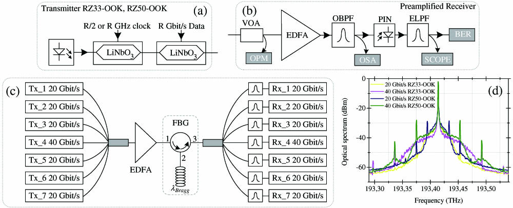
The simulation setup for study of all-optical RZ–OOK to NRZ–OOK modulation format conversion with single uniform FBG filter in MLR DWDM system is illustrated in Fig. 1(c). The setup consists of three parts: optical transmitter, all-optical modulation format converter, and preamplified optical receiver. The optical transmitter [Fig. 1(a)] for 20 and 40 Gbit/s RZ33–OOK and RZ50–OOK optical signal generation consists of continuous wave (CW) light laser and two Mach–Zehnder modulators (MZMs). The optical spectrums of modulation formats used in conversion are illustrated in Fig. 1(d). The first MZM was used as a pulse carver driven by a half or full clock (depending on the duty cycle for RZ signal), while the second one was driven by 20 or 40 Gbit/s pseudo-random binary sequence (PRBS) with a pattern length of .

Figure 1.Setup for modulation format conversion: (a) RZ–OOK transmitter; (b) optical receiver; (c) system configuration; (d) 20 and 40 Gbit/s 33% and 50% duty cycle RZ–OOK spectra.
The optical signal was then coupled into the all-optical modulation format converter which consists of uniform FBG filter and raised cosine (RC) optical band-pass filter (OBPF) used only for channel separation. We used amplitude and phase information to model optical filters. The pass-band of RC OBPF is wide (60 GHz for 20 Gbit/s and 100 GHz for 40 Gbit/s signals) to have negligible penalty from linear crosstalk and phase response. This was confirmed in simulations without uniform FBG model in the setup. Setup was built to have negligible impact on modulation format conversion. In this work three all-optical modulation format converters were used to see the impact of amplitude noise from uniform FBG contrast profile on conversion efficiency. The uniform FBG has rather high insertion loss for central channel, because of requirement for side lobes to have appropriate bandwidth between two notches and Gaussian like shape to reduce amplitude fluctuations in converted signal. Therefore weak gratings were used in simulations. Amplitude transfer functions of uniform FBG filters and RC OBPF are shown in Fig. 2(a). After converter 20 or 40 Gbit/s NRZ–OOK optical signal was detected in a preamplified receiver [Fig. 1(b)]. This receiver consists of variable optical attenuator (VOA), optical power meter (OPM), erbium-doped fiber amplifier (EDFA), 200 GHz Gaussian optical OBPF, photodiode, electrical low-pass filter (ELPF), optical spectrum analyzer (OSA), electrical scope, and bit-error rate (BER) tester. In this current configuration MLR DWDM system has seven channels.
Figure 2.(a) Uniform FBG and RC filters amplitude transfer functions used in the setup; (b) “1” level amplitude ripples evaluation with coefficient.
Channels allocation on the frequency grid was in accordance with uniform FBG transfer function which is shown in Fig. 2(a). MLR DWDM system has seven channels. The line rate for the middle channel is 40 Gbit/s and for rest, 20 Gbit/s. Channel spacing for the system is 100 GHz between 40 and 20 Gbit/s channels and 75 GHz between 20 and 20 Gbit/s channels to avoid significant linear crosstalk between neighboring channels. The “1” level amplitude ripple was evaluated for converted NRZ–OOK signal with coefficient which is defined in Fig. 2(b). The coefficient in the case of ideal RZ–OOK signal (see the red eye diagram) has value of 1 and in the case of ideal NRZ–OOK signal (see the blue eye diagram) has the value of zero. By taking in to account some of the physical parameters of the devices used in the work the lines of the eye diagram gets broader mainly due to optical and electrical noise and “1” level amplitude ripple gets higher in the process of nonideal all-optical modulation format conversion. Coefficient will be used in a subsequent paragraph.
Figure 3 shows the back-to-back (BTB) optical spectrums for RZ33–OOK and RZ50–OOK signals and NRZ–OOK optical spectra after all-optical modulation format converters with 0%, 10%, and 30% amplitude noise in the uniform contrast profile. The undesired side peak suppression and spectral shaping needed for modulation format conversion is quite efficient in both cases for RZ33–OOK and RZ50–OOK signals. The modulation format converter with 30% amplitude noise value shows the worst performance especially for 20 Gbit/s line-rate channels when side peaks are suppressed inefficiently and spectrums appears to be asymmetrical. This leads to large “1” level amplitude ripples.
Figure 3.Optical spectra for (a) RZ33–OOK and (b) RZ50–OOK in MLR DWDM system (resolution bandwidth, 0.01 nm).
The BER as a function of received power for modulation format conversion in fourth channel with 40 Gbit/s line rate for MLR DWDM system with RZ33–OOK modulation format is illustrated in Fig. 4(a) and with RZ50–OOK modulation format in Fig. 4(f). The insets include eye diagrams of BTB RZ33–OOK and RZ50–OOK signals and converted NRZ–OOK signals. It can be observed that RZ33–OOK eye diagrams have more amplitude ripple and the BER performance is worse. This could be explained with optical spectrum difference between 33% and 50% duty cycle signals [Fig. 1(d)]. Amplitude noise in the uniform contrast profile has negligible impact on the all-optical modulation format conversion up to value of 10% since the depth of main lobe notches of the transfer function [Fig. 2(a)] are not reduced significantly.
Figure 4.BER as a function of received power: (a) RZ33–OOK and (f) RZ50–OOK to NRZ–OOK modulation format conversion with different uniform FBG filters for fourth channel in MLR DWDM system. Insets, eye diagrams of B2B; (b) RZ33–OOK and (g) RZ50–OOK signals and converted NRZ–OOK signals after modulation format converters with (c) and (h) 0%, (d) and (i) 10%, and (e) and (j) 30% amplitude noise in uniform contrast profile.
BER as a function of received power for modulation format conversion in first channel with 20 Gbit/s line rate for MLR DWDM system with RZ33–OOK modulation format is illustrated in Fig. 5(a) and with RZ50–OOK modulation format in Fig. 5(f). The results from worst channel were shown. Other 20 Gbit/s channels showed better performance even for 30% case. The insets include eye diagrams of BTB RZ33–OOK and RZ50–OOK signals and converted NRZ–OOK signals. Similar to the 40 Gbit/s case the better performance is obtained for RZ50–OOK modulation format. Amplitude noise in the uniform FBG contrast profile has small impact until the 10%, but for higher values the amplitude ripple of the “1” level is close to the whole amplitude values. This shows that modulation conversion is not obtained since the depth of side lobe notches in the transfer function [Fig. 2(a)] are greatly affected.
Figure 5.BER as a function of received power: (a) RZ33–OOK and (f) RZ50–OOK to NRZ–OOK modulation format conversion with different uniform FBG filters for first channel in MLR DWDM system. Insets, eye diagrams of B2B; (b) RZ33–OOK and (g) RZ50–OOK signals and converted NRZ–OOK signals after modulation format converters with (c) and (h) 0%, (d) and (i) 10%, and (e) and (j) 30% amplitude noise in uniform contrast profile.
Power penalty for RZ33–OOK to NRZ–OOK converted seven channels in MLR DWDM system is illustrated in Fig. 6(a). It can be seen that slightly higher penalty values are for channels with 20 Gbit/s line rate. The same observation could be seen from the eye diagrams. The amplitude ripple is more severe comparing to the 40 Gbit/s line rate. Thirty percent of amplitude noise in the uniform contrast profile is too large to ensure modulation format conversion as shown in the Fig. 6(d). This could be also an explanation for smaller power penalty. The spectrum of the channel is less affected by depths of the notches in the side lobes from uniform FBG transfer function as illustrated in Fig. 2(a).
Figure 6.(a) Power penalty for MLR RZ33–OOK DWDM system and eye diagrams for converted 20 Gbit/s NRZ–OOK after modulation format converters with (b) 0%, (c) 10%, and (d) 30% amplitude noise in uniform contrast profile and 40 Gbit/s NRZ–OOK after modulation format converters with (e) 0%, (f) 10%, and (g) 30% amplitude noise in uniform contrast profile.
Power penalty for RZ50–OOK to NRZ–OOK converted seven channels in MLR DWDM system is illustrated in Fig. 7(a). Similarly to 33% duty cycle it can be seen that slightly higher penalty values are for channels with 20 Gbit/s line rate. The power penalty is around 2 dB less comparing to RZ33–OOK signal. It can be seen that only partial modulation format conversion have been observed for the 20 Gbit/s RZ50–OOK signal as it is shown in Fig. 7(d). This is due to the insufficient depth of the side lobe notches in the modulation format converter.
Figure 7.(a) Power penalty for MLR RZ50–OOK DWDM system and eye diagrams for converted 20 Gbit/s NRZ–OOK after modulation format converters with (b) 0%, (c) 10%, and (d) 30% amplitude noise in uniform contrast profile and 40 Gbit/s NRZ–OOK after modulation format converters with (e) 0%, (f) 10%, and (g) 30% amplitude noise in uniform contrast profile.
factor as a function of uniform FBG central frequency offset for 40 and 20 Gbit/s RZ–OOK to NRZ–OOK modulation format conversion is illustrated on Fig. 8. This was performed to study the device fabrication tolerances impact on the modulation format conversion efficiency. The results are similar to the previously reported[17] for the single-channel case when slight detuning of the filter central frequency and channel central frequency could increase the signal quality. But the difference is that RZ50–OOK has better modulation format conversion efficiency comparing to the RZ33–OOK which is shown in the obtained results.
Figure 8. factor as a function of offset between uniform FBG central wavelength and channel central wavelength for (a) 40 and (b) 20 Gbit/s RZ–OOK to NRZ–OOK modulation format conversion in MLR DWDM system.
The coefficient [defined in Fig. 2(b)] as a function of uniform FBG central frequency offset for 40 and 20 Gbit/s RZ–OOK to NRZ–OOK modulation format conversion is illustrated in Fig. 9. The amplitude noise impact from the uniform FBG contrast profile has large impact when it is greater than 20% especially for the 20 Gbit/s channels with RZ33–OOK modulation format. The coefficient values are equal to 1 which shows that signal is with RZ pulse shape.
Figure 9.Coefficient as a function of offset between uniform FBG central wavelength and channel central wavelength for (a) 40 and (b) 20 Gbit/s RZ–OOK to NRZ–OOK modulation format conversion in MLR DWDM system.
In conclusion, we study 40 and 20 Gbit/s RZ–OOK signals with 33% and 50% duty cycles conversion to NRZ–OOK signals in single uniform FBG with 21% reflectivity for MLR DWDM systems. For 40 Gbit/s line-rate signal negligible amplitude ripple were observed even for large value of FBG central frequency offset and bit-rate deviation. The conversion of MLR system configuration has been shown with some indication on the manufacturing tolerances of the uniform FBG.
References
[1] R. Essiambre, R. W. Tkach. Proc. IEEE, 100, 1035(2012).
[2] P. J. Winzer, R. Essiambre. Proc. IEEE, 94, 952(2006).
[3] C. H. Kwok, S. H. Lee, K. K. Chow, C. Lin. IET Optoelectron., 1, 47(2007).
[4] W. Astar, J. B. Driscoll, L. Xiaoping, J. I. Dadap, W. M. J. Green, Y. A. Vlasov, G. M. Carter, R. M. Osgood. IEEE J. Sel. Top. Quantum Electron., 16, 234(2010).
[5] Y. Yu, X. Zhang, H. Dexiu, L. Li, W. Fu. IEEE Photon. Technol. Lett., 19, 1027(2007).
[6] Y. Ding, C. Peucheret, M. Pu, B. Zsigri, J. Seoane, L. Liu, J. Xu, H. Ou, X. Zhang, D. Huang. Opt. Express, 18, 21121(2010).
[7] Y. Zhan, M. Zhang, M. Liu, L. Liu, X. Chen. Chin. Opt. Lett., 11, 030604(2013).
[8] J. W. Wu. Infrared Phys. Technol., 54, 465(2011).
[9] P. Honzatko, M. Karásek. Opt. Commun., 283, 2061(2010).
[10] Y. Zhang, L. Yi, T. Zhang, Z. Li, W. Hu. Chin. Opt. Lett., 11, 100601(2013).
[11] L. Xiang, D. Gao, B. Zou, S. Hu, X. Zhang. Sci. China Technol. Sci., 56, 558(2013).
[12] P. Groumas, V. Katopodis, C. Kouloumentas, M. Bougioukos, H. Avramopoulos. IEEE Photon. Technol. Lett., 24, 179(2012).
[13] M. Xiong, O. Ozolins, Y. Ding, B. Huang, Y. An, H. Ou, C. Peucheret, X. Zhang. Opt. Express, 20, 27263(2012).
[14] X. Dong, P. Guo, Y. Xie. Opt. Fiber Technol., 21, 87(2015).
[15] O. Ozolins, V. Bobrovs, G. Ivanovs. Proceedings of 55th International Symposium ELMAR 2013, 121(2013).
[16] O. Ozolins, V. Bobrovs, G. Ivanovs. Opt. Photon. J., 3, 337(2013).
[17] H. Cao, X. Shu, J. Atai, Q. Dong, J. Zuo, G. J. Chen, Y. Yu. Chin. Opt. Lett., 12, 090603(2014).
[18] H. Cao, X. Shu, J. Atai, A. Gbadebo, B. Xiong, T. Fan, H. Tang, W. Yang, Y. Yu. Opt. Express, 22, 30442(2014).
[19] H. Cao, J. Atai, Y. Yu, Q. Dong, J. Zuo, G. J. Chen, X. Shu. Proceedings of PIERS 2014, 2060(2014).