• Chinese Optics Letters
  • Vol. 17, Issue 3, 030501 (2019)
Huashan Yang1、2, Fuling Zhang3, Lemeng Leng1、2, Zhaobang Zeng1、2, Yue Shao1、2, Hui Zhang3, Nan Yang1、2, and Xiangning Chen4、*
Author Affiliations
  • 1College of Engineering and Applied Sciences, Nanjing University, Nanjing 210093, China
  • 2Key Laboratory of Intelligent Optical Sensing and Manipulation of Ministry of Education, Nanjing University, Nanjing 210093, China
  • 3The 27th Research Institute of China Electronics Technology Group Corporation, Zhengzhou 450047, China
  • 4School of Electronic Science and Engineering, Nanjing University, Nanjing 210093, China
  • show less
    DOI: 10.3788/COL201917.030501 Cite this Article Set citation alerts
    Huashan Yang, Fuling Zhang, Lemeng Leng, Zhaobang Zeng, Yue Shao, Hui Zhang, Nan Yang, Xiangning Chen. Grating coupler efficiency enhancement by double layer interference[J]. Chinese Optics Letters, 2019, 17(3): 030501 Copy Citation Text show less
    (a) Proposed GC efficiency enhancing scheme with an 8° polished APF with its facet parallel to the chip surface. (b) Cross-sectional schematic of the 2D-FDTD model of a GC coupling with an 8° tilted APF. (c) Schematic of the light interferences in the air gap layer.
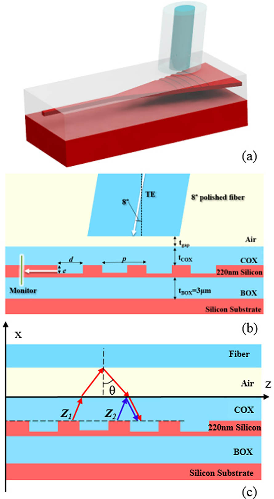
    Fig. 1. (a) Proposed GC efficiency enhancing scheme with an 8° polished APF with its facet parallel to the chip surface. (b) Cross-sectional schematic of the 2D-FDTD model of a GC coupling with an 8° tilted APF. (c) Schematic of the light interferences in the air gap layer.
    (a) Surface plot for simulated CE with different tCOX and tgap. (b) Simulated insertion loss of the GC with 1.84 μmtCOX (blue) and 1.57 μmtCOX (red) coupling with an APF (solid line) and a 12° tilted SMF (dashed line) with tgap from 0.5 to 1.5 μm. (c) Simulated transmission (solid line) and reflection (dashed line) spectra of APF (red) and 12° tilted SMF (blue) coupled GC with 1.84 μmtCOX.
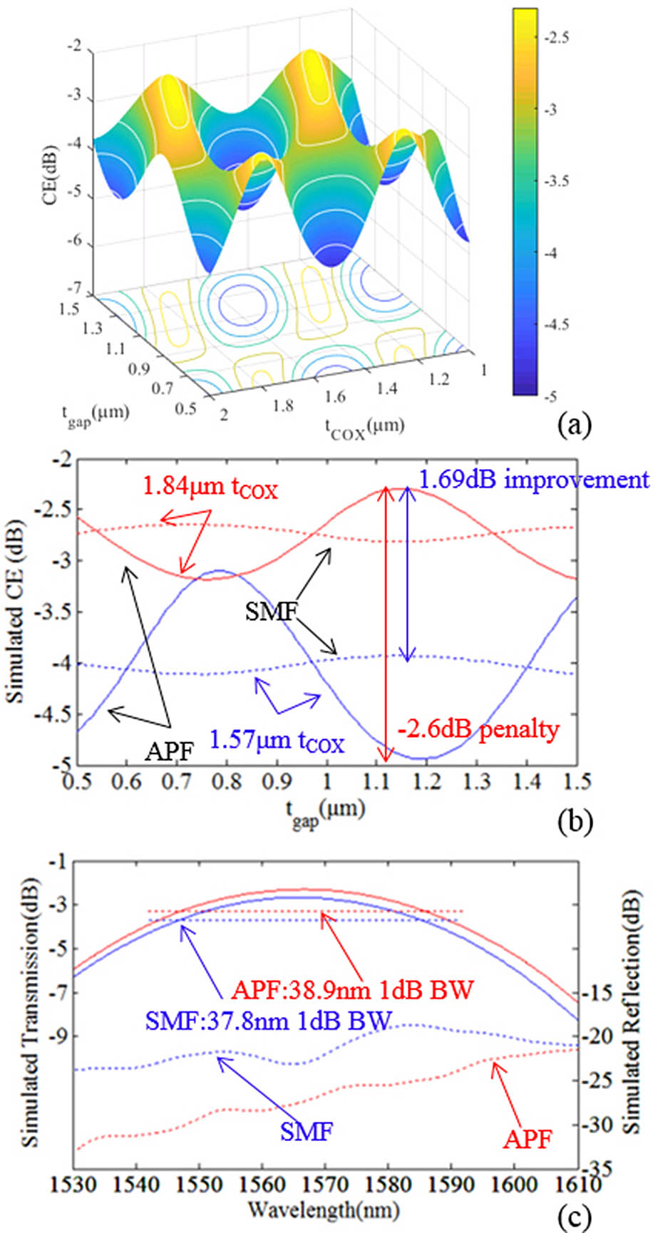
    Fig. 2. (a) Surface plot for simulated CE with different tCOX and tgap. (b) Simulated insertion loss of the GC with 1.84μmtCOX (blue) and 1.57μmtCOX (red) coupling with an APF (solid line) and a 12° tilted SMF (dashed line) with tgap from 0.5 to 1.5μm. (c) Simulated transmission (solid line) and reflection (dashed line) spectra of APF (red) and 12° tilted SMF (blue) coupled GC with 1.84μmtCOX.
    (a) Simulated enhancing effect of the air gap at different tilting and polishing angles. (b) Peak CE drops 0.15 dB as tgap increases to 10 μm.
    Fig. 3. (a) Simulated enhancing effect of the air gap at different tilting and polishing angles. (b) Peak CE drops 0.15 dB as tgap increases to 10μm.
    (a) Fiber alignment tolerance in the z direction for the APF (red) and SMF (blue). (b) Enhancing effect by directionality only and various tgap APF with different tCOX. (c) Maximum enhancing effect at various tgap (red) and directionality’s 1.06 dB enhancing effect.
    Fig. 4. (a) Fiber alignment tolerance in the z direction for the APF (red) and SMF (blue). (b) Enhancing effect by directionality only and various tgap APF with different tCOX. (c) Maximum enhancing effect at various tgap (red) and directionality’s 1.06 dB enhancing effect.
    (a) Simulated (solid line) and measured (× mark) GC insertion loss with tcox from 1.2 to 1.9 μm coupling with an APF with 5.4 μmtgap. Inset: optical microscopy image of the “GC loop”. (b) Measured transmission spectra of the GC with 1.23 μm COX coupling with SMF (blue) and APF (red).
    Fig. 5. (a) Simulated (solid line) and measured (× mark) GC insertion loss with tcox from 1.2 to 1.9μm coupling with an APF with 5.4μmtgap. Inset: optical microscopy image of the “GC loop”. (b) Measured transmission spectra of the GC with 1.23μm COX coupling with SMF (blue) and APF (red).
    Huashan Yang, Fuling Zhang, Lemeng Leng, Zhaobang Zeng, Yue Shao, Hui Zhang, Nan Yang, Xiangning Chen. Grating coupler efficiency enhancement by double layer interference[J]. Chinese Optics Letters, 2019, 17(3): 030501
    Download Citation