In order to solve the problem of low measurement accuracy caused by uneven imaging resolutions, we develop a three-dimensional catadioptric vision sensor using 20 to 100 lasers arranged in a circular array called omnidirectional dot maxtric projection (ODMP). Based on the imaging characteristic of the sensor, the ODMP can image the area with a high image resolution. The proposed sensor with ODMP can minimize the loss of the detail information by adjusting the projection density. In evaluating the performance of the sensor, real experiments show the designed sensor has high efficiency and high precision for the measurement of the inner surfaces of pipelines.
In computer vision systems, omnidirectional three-dimensional (3D) measurements are an attractive area that can observe omnidirectional scenes simultaneously[1,2]. The imaging model of catadioptric vision systems have been studied in-depth in recent years. Geyer and Daniilidis[3] derived the geometric model of the catadioptric camera system, which has been used by many research works in the area of visual serving. Scaramuzza et al.[4,5] gave a detail analysis of the catadioptric camera’s imaging model with a conic reflector. Similarly, vision sensors based on the catadioptric vision system also have achieved remarkable results. Paniagua et al.[6] designed a wearable catadioptric vision sensor with a low-cost conic pattern laser in hand. Shin[7] proposed an omnidirectional ranging system using a line structured light image to obtain all directional distance information effectively. Harmat[8] presented an omnidirectional structure light sensor that could be applied to small, unmanned aerial vehicles, which can operate in a number of different environments. Zhang[9] used light rings with different angular frequencies and intensities to build a catadioptric vision system for robotic navigation. Catadioptric camera systems based on structured light 3D vision measurements have the widest applications[10–13] in practical inspections due to their fast measuring speed, non-contact, low cost, and robust nature in real measurements[14–16]. However, although the working method and principle of the existing catadioptric structured light vision sensors are similar, the lasers used in the sensors are different, such as circular structured light and line structured light[17], which may cause the loss of detail information in a local, highly reflective pipeline. The measurement accuracy is influenced by the uneven imaging resolution caused by the structure characteristics of the reflector and the projection density of the lasers.
To solve these problems, we present a 3D catadioptric vision sensor that can be applied to the measurement of a long pipeline. The omnidirectional dot maxtric projection (ODMP), which consists of 20 to 100 dot lasers and is positioned in 2 to 5 layers between the mirror and camera by 10° to 50°, can image a high imaging resolution area. The density of the ODMP can be adjusted using the measurement accuracy. In the following section, we describe how we can realize the measurement model by using the ODMP.
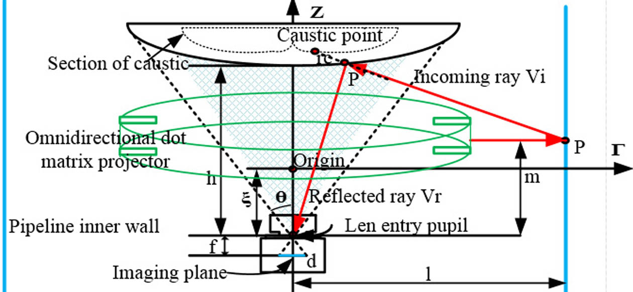
To measure the detail information of the inner surface, we first established the structure of the sensor. Figure 1 shows the optical path designation of the ODMP sensor. The camera placed below the conic reflector and the camera optical axis coincide with the symmetry axis of the conic reflector in the vertical direction. As is shown in Fig. 1, there are some identifiers that need introducing: the entrance pupil of the lens is located at unite above the origin. is the distance between the optical center of the camera and the vertex of the conic reflector. The working height of the ODMP is . The working distance of the novel sensor is set as the minimum distance from the light spots in the omnidirectional image to the camera optical axis, which is defined as .
Sign up for Chinese Optics Letters TOC. Get the latest issue of Chinese Optics Letters delivered right to you!Sign up now
In order to make the system compact and choose the appropriate lens, the field of view (FOV) angle is determined by the focal length of the lens and the CCD camera size, which is : Then, we define the point on the reflector surface[4] as : where is the eccentricity and is the focus of the conic section. From Fig. 1, given one point in 3D space, the coordinates of are . The vectors along the incoming ray and reflected ray are given by
Because of the singularity of the point on the caustic, the determinant of the Jacobian must vanish. For the class of conic catadioptric cameras, we can derive using where is the distance of the scene point from the reflector. Since we know the geometry of the reflector, its surface normal can be derived analytically. Reflecting and incoming are symmetrical about the surface normal . We can derive the working height of laser projector as
As is shown in Fig. 2, the height of the reflector is the depth of field . and are the far depth of field and the near depth of field, respectively. is the diameter of the circle of confusion. is the lens aperture. The value of in the -axis set is the focus of the curved mirror. Because the reflector needs to occupy the overall FOV of the camera, we can design the shape of the reflector, and the formula to compute is
Figure 2.Principle model of reflector designation.
Then, we analyze the effect of such a view surface on the resolution characteristics of the sensor. As is shown in Fig. 3, an infinitesimal area with the angle in the image plane projects into the reflector as a region of area through the entry pupil of the lens. Let an infinitesimal solid angle between this area image and the scene be . The resolution of this sensor is defined as . Thus, the solid angle visible at the infinitesimal region and the resolution of the image system is an inversely proportional relationship[5].
Figure 3.Resolution model of multi-dot-field local reconstruction sensor.
The distance from the image point to the entrance pupil corresponding to is . The solid angle subtended by the foreshortened area at the entrance pupil of the lens is
Then, the area projected into the reflector by is derived using where is the angle between the reflected ray for the area and the surface normal at area . Then, the incoming angle of the scene point is . The resolution for the omnidirectional catadioptric vision system can be obtained using
We now present the model of measurement accuracy for the ODMP sensor. Using Fig. 4, some known geometry coordinates are defined in the catadioptric model, such as , , and . Given world point , is the point projected on the reflector, and the point in the normalized camera coordinate is . Their relationships are derived based on the model of the reflector’s surface: where is the constant that describes the relationship between points and . Since the points and are collinear along the incoming ray direction, the relationship of , and can be obtained using where and are the rotation matrix and the translation vector, respectively.
Figure 4.Measurement model of multi-dot-field local reconstruction sensor.
Then, we established a dot matrix plane to test the accuracy of the dot matrix projection using the ODMP. The point satisfies the equation of the dot matrix plane , . Then, the equation of the dot matrix plane can be determined using where are the coefficients of the dot matrix plane equation. Therefore, the 3D information of the dot matrix plane can reconstructed by computing the coordinates of :
In summary, the overall measurement system using the ODMP and described through Eqs. (1)–(14) is as follows: Check the structure of the catadioptric structured light vision sensor using Eqs. (1)–(6);According to the structure of the sensor, finding the best image resolution of the non-central catadioptric system from Eqs. (7)–(9);Verify the measurement accuracy of the sensor using the ODMP values from Eqs. (10)–(14).
We now apply results to find the best mirrors fitted with the 3D catadioptric vision sensor and study their resolution characteristics to see which can get the highest resolution.
In order to verify the accuracy of the 3D catadioptric vision sensor, let the working distance in the horizontal direction of the sensor be , and the working distance in the vertical direction of the sensor is . We select a high-speed camera whose focal length is . Based on Eqs. (1)–(7), the depth of field is . The detail configuration based on the designed model is shown in Table 1. In order to find the right mirror shape, we analyzed three commonly used mirrors: a hyperbolic mirror, a parabola mirror, and an ellipse mirror.
Category
Parameters
Camera
Interface: GigE vision
Resolution: 2456(H)×2058(V)
Pixel size: 3.5(μm)×3.5(μm)
Optic size: (2/3) in.
Frame rate: 15 fps
Lens
Focal length: 12 mm
Lens aperture F: 10 mm
Horizontal angle of view: 49.25°
Dimensions: 29.5mm(D)×28.5mm(L)
The diameter of circle of confusion: 0.033 mm
Center dot projector
Size: ϕ12×35mm
Wavelength: 650 nm
Operating voltage: DC 5 V
Fan angle: 90°
Output power: 2.5 mW
Table 1. Configuration of Multi-Dot-Field Local Reconstruction Sensor
In Fig. 5, we chose three results in different shapes with the best effects (). For the ellipse reflector, the resolution drops drastically. However, the resolution characteristics of the hyperbola and parabola reflectors gradually change towards the edge of the reflector, and the resolution of the hyperbola is better than that of the parabola.
Figure 5.Resolution characteristics of the three reflectors.
Considering the class of reflector models analyzed in Fig. 5, we choose the hyperbola reflector. Given the hyperbola reflector, we can fit the right parameters in the model based on extreme points on the caustic and choose a projection area that has a high resolution that is better than the parabola. The designation results of the hyperbola mirror are shown in Table 2, and Fig. 6 shows the shape of the designed hyperbola mirror.
Figure 6.Shape of designed hyperbola reflector ().
Then, based on the above analysis, the final projection area, calculated by the change of the incident angle, needs to be in the best position for projection. The resolution drops drastically when the incident angle is larger than 120°, as shown in Fig. 7.
Figure 7.Influence of angle of view field with resolution.
Therefore, combining the results in Figs. 5 and 7, the best area for projection can be obtained and the imaging area with the highest resolution is [7.25, 22.32]. The subsurface radius of the hyperbola reflector is at least 25 mm to guarantee image quality. Then, we considered the camera and reflector as a whole and selected three wavelengths (, , and ) to verify the image resolution quality. Then we applied the Rayleigh criterion and Strehl’s theory to analyze the image quality of the ODMP.
Figure 8 shows the deformation degree of an emergent wave surface. In Fig. 9, the abscissa is the enclosed circle radius of the Gaussian image point, and the ordinate is the energy included in the enclosed circle. The fraction of enclosed energy is larger than 0.8, so the process of imaging is complete. The modulus of the optical transfer function are applied to test the resolution quality of the whole imaging process, as is shown in Fig. 10.
In Fig. 10, we can see that both the high frequency and low frequency parts have a high contrast. In the imaging system, we can obtain images with high resolutions.
Last, the accuracy of the sensor is verified by comparing two values, as described previously. One is the basic value defined as the position of the calibration target from the scene, and the other is a measurement value defined as the fitting surface, which is the dot matrix plane using the dot matrix projection, as shown in Fig. 11.
Then, we placed the target at a random position for local imaging and calculated the error of the designed sensor. Those data can apply to the verification of the sensor measurement accuracy because they are not used for the calibration.
Figure 12 shows the experimental image with the ODMP; we placed the calibration target at four different positions. The fitting calibration target can be reconstructed using the dot matrix projector. The experimental results are shown in Fig. 13.
Considering the fitting calibration target reconstructed by the dot matrix projection, we analyzed the RMS error with the real calibration target, which is calculated by the process of traditional catadioptric calibration[4], as shown in Fig. 14. The RMS error of the fitting calibration target is decreased with the increase of the dot matrix.
Then, we collected an image ( ODMP) used an ordinary hyperbola reflector to compare the proposed sensors. The compared errors in the , , and directions between the proposed sensor and the ordinary are shown in Figs. 15 and 16.
Figure 15.Compared measurement error in , , directions.
In Fig. 15, the fluctuations of the errors in the , , and directions are small and have good robustness. Moreover, the proposed measurement model has high accuracy in the , , and directions, as shown in Fig. 16.
In conclusion, the presented sensor consists of a traditional perspective camera, a hyperbola reflector, and the ODMP. Its mathematical geometric senor model is constructed. The model is simple. Moreover, by analyzing the characteristics of the conic reflector, we obtain an area with a high resolution to decrease the difference of resolution in the reflector surface. The key of the catadioptric vision sensor is that it can minimize the loss of detail information in the process of measurement. The density of the ODMP can adjust to the different requirements in the measurement procedure. The encouraging results prove that this sensor is feasible for accurate catadioptric structure light vision measurement applications.