
Jinghua Zhang, Yan Zhang, Zhiguang Shi, Biao Li, Yu Zhang, Di Liu, Yuchang Suo. Reflected Light Separation on Transparent Object Surface Based on Normal Vector Estimation[J]. Acta Optica Sinica, 2021, 41(15): 1526001
- Acta Optica Sinica
- Vol. 41, Issue 15, 1526001 (2021)
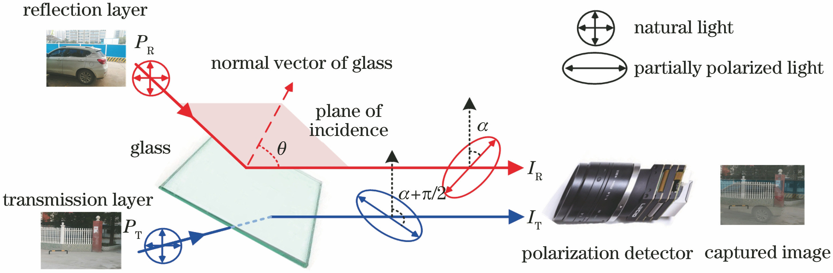
Fig. 1. Components of light on transparent object’s surface

Fig. 2. Simulation results. (a) Reflectivity and polarization degree of reflected light; (b) transmissivity and polarization degree of transmitted light
Fig. 3. Diagram of transmission of polarization state of light waves on surface of transparent object
Fig. 4. Process of solving azimuth angle of incident plane at central point. (a) Image of polarization angles; (b) Histogram of central pixel block in image of polarization angles
Fig. 5. Reflected light scenes. (a) Transmitted light image; (b) reflected light image; (c) polarization image in vertical direction; (d) polarization image in parallel direction
Fig. 6. Reflected light separation results when χ=0.2 and γ=0.2, 0.4, 0.8. (a) γ=0.2; (b) γ=0.4; (c) γ=0.8
Fig. 7. NCC curves in different γ. (a) NCC curve of point P1; (b) NCC curve of point P2
Fig. 8. Extraction of zero-crossing pixels and variation curves of correlation value with viewing angle. (a) NCC between over-separated transmitted light image and under-separated transmitted light image; (b) extraction result of zero-crossing pixels; (c) variation curve of mutual information with viewing angle; (d) fR(δ,φ) versus viewing angle
Fig. 9. Flow diagram of proposed algorithm
Fig. 10. Schematic diagram of reflected light data collection
Fig. 11. Polarization images of indoor scene. (a) True transmitted light image; (b) 0° polarization image; (c) 45° polarization image; (d) 90° polarization image; (e) 135° polarization image; (f) polarization image in parallel direction; (g) polarization image in vertical direction; (h) viewing angle image; (i) azimuth angle image
Fig. 12. Polarization images of outdoor scene. (a) True transmitted light image; (b) 0° polarization image; (c) 45° polarization image; (d) 90° polarization image; (e) 135° polarization image; (f) polarization image in parallel direction; (g) polarization image in vertical direction; (h) viewing angle image; (i) azimuth angle image
Fig. 13. Reflected light separation results of indoor scene. (a1)(a2) Proposed algorithm; (b1)(b2) algorithm in Ref. [2]; (c1)(c2) algorithm in Ref. [10]; (d1)(d2) algorithm in Ref. [11]
Fig. 14. Reflected light separation results of outdoor scene. (a1)(a2) Proposed algorithm; (b1)(b2) algorithm in Ref. [2]; (c1)(c2) algorithm in Ref. [10]; (d1)(d2) algorithm in Ref. [11]
|
Table 1. Quantitative comparison of separation effects of reflected light under different methods

Set citation alerts for the article
Please enter your email address
© Copyright 2018-2021 | Chinese Laser Press. All Rights Reserved 沪ICP备15018463号-20