
Yiqing CAO, Zhijuan SHEN, Lijun LYU. Aberration optimization method for aspherical catadioptric imaging system with large acceptance aperture based on sixth-order wave aberration theory[J]. Chinese Journal of Quantum Electronics, 2024, 41(1): 67
- Chinese Journal of Quantum Electronics
- Vol. 41, Issue 1, 67 (2024)
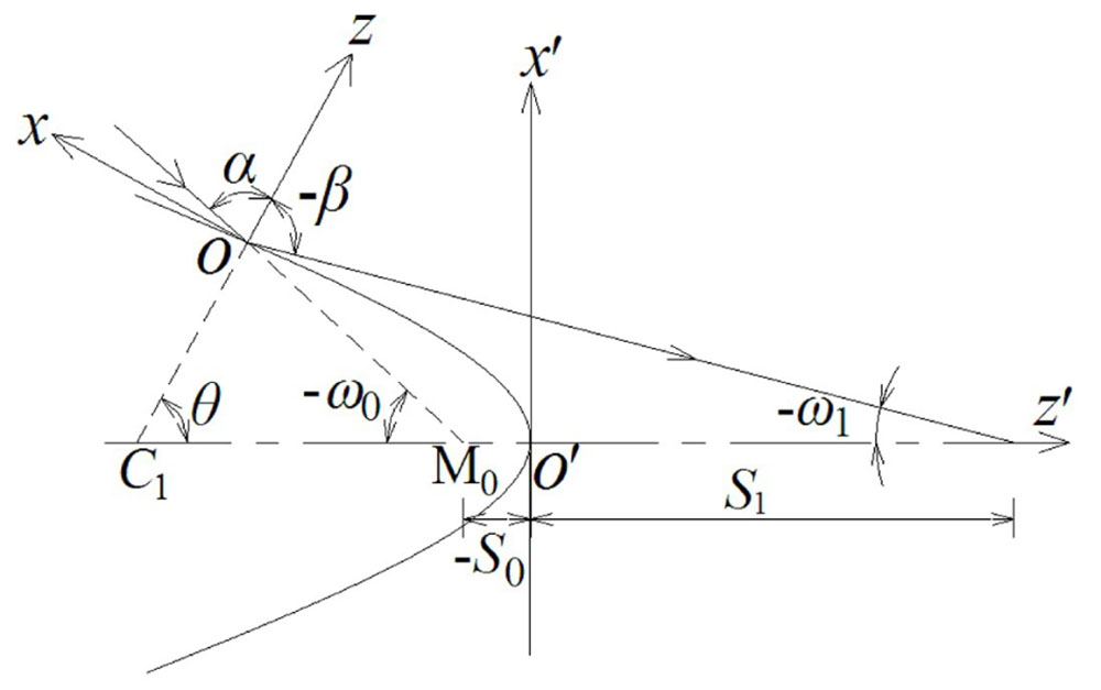
Fig. 1. Propagation diagram of the chief ray at a quadrics of revolution
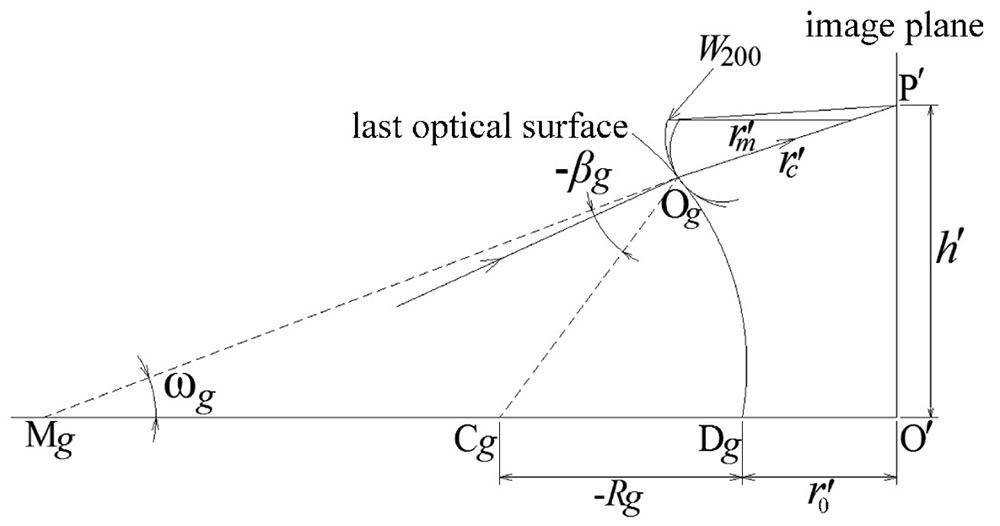
Fig. 2. Optical scheme of the chief ray passing the
Fig. 3. Flow chart for aberration optimization of catadioptric imaging system with large acceptance aperture
Fig. 4. Initial structure and optical scheme of catadioptric imaging system with large accptance aperture
Fig. 5. MTF curves of catadioptric imaging system with large acceptance aperture in the case of initial structure
Fig. 6. Spot diagram with field angles at 5°, 25°, 45° and 60° of catadioptric imaging system with large acceptance aperture in the case of initial structure
Fig. 7. MTF curves of catadioptric imaging system with large acceptance aperture obtained using proposed aberration optimization method
Fig. 8. Spot diagram with field angles at 5°, 25°, 45° and 60° of catadioptric imaging system with large acceptance aperture obtained using proposed optimization method
|
Table 1. Initial structure parameters of catadioptric imaging system with large acceptance aperture
|
Table 2. Optical structure parameters of catadioptric imaging system with large acceptance aperture obtained using proposed aberration optimization method
| |||||||||||||||
Table 3. RMS of the spot diagram given in Fig. 6
| |||||||||||||||
Table 4. RMS of the spot diagram given in Fig. 8

Set citation alerts for the article
Please enter your email address
© Copyright 2018-2021 | Chinese Laser Press. All Rights Reserved 沪ICP备15018463号-20