
Kai Yang, Ruiqi Mao, Qiang An, Zhanshan Sun, Yunqi Fu, "Laser frequency locking method for Rydberg atomic sensing," Chin. Opt. Lett. 21, 021407 (2023)
- Chinese Optics Letters
- Vol. 21, Issue 2, 021407 (2023)
Abstract
1. Introduction
In the past decade, Rydberg atomic electrometry has made substantial progress in the measurements of electromagnetic field amplitude[1–4], polarization[5], phase[6], and angle[7]. In these experiments, a weak probe laser excited the alkali metal atoms from their ground state to the intermediate state; meanwhile, an intense coupling laser excited the atoms from the intermediate state to a Rydberg state, forming an optical transmission window, which is known as electromagnetically induced transparency (EIT). The presence of an electromagnetic field will disrupt the EIT spectrum and change the optical transmission according to the AC Stark effect. When the frequencies of both the probe and coupling lasers are locked to the atomic transition, the electromagnetic field variation can be detected by the change of the probe laser transmission. Hence, the frequency stability of the probe and coupling lasers is a crucial technique for Rydberg atomic sensing, especially in the case of heterodyne scenarios[6–9].
In general, active laser frequency stabilization techniques can be roughly divided into two categories. One is locking the laser frequency to an external optical reference cavity, such as the Pound–Drever–Hall (PDH) method[10–14]. The other is using atomic transition spectroscopy for laser frequency stabilization, such as saturated absorption spectroscopy (SAS)[15], polarization spectroscopy[16], modulation transfer spectroscopy[17], and recently, EIT spectroscopy[18–20]. The cavity-locking methods are susceptible to environmental factors such as pressure and temperature and require additional means to shift the laser frequency to the atomic resonance transition, since the reference is the cavity rather than the atomic level. In contrast, the atomic transition spectral-locking methods can stabilize the laser frequency directly at the atomic resonance transition and are robust to external disturbances so that they can be one of the promising candidates for practical applications.
This work presents a simultaneous dual-wavelength locking method for Rydberg atom-based sensing by multiplexing the modulation signal. Based on the well-established modulated transfer spectroscopy technique, we extracted a portion of the modulated probe light that counterpropagates with an intense coupling light to generate the modulated EIT and the corresponding error signal. Then, we analyzed the variance of error signals under different probe and coupling laser powers. The Allan variance is introduced to evaluate the frequency stability of the coupling laser. Furthermore, the performance of our laser frequency stabilization technique was then assessed using a 10 kHz amplitude-modulated (AM) signal, which is one of the practical application scenarios for Rydberg atomic sensing. According to the ladder-type Rydberg EIT of cesium atoms, the probe laser is locked to the transition from the ground state (
Sign up for Chinese Optics Letters TOC. Get the latest issue of Chinese Optics Letters delivered right to you!Sign up now
2. Experimental Setup
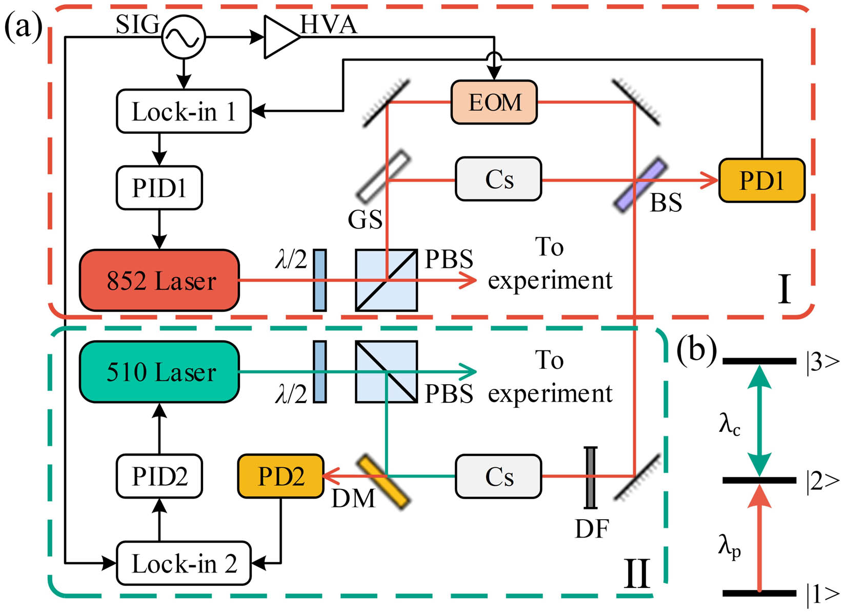
The sketch of the experimental setup and the related three-level Rydberg ladder EIT are shown in Fig. 1. In Fig. 1(b), one can see that the 510 nm coupling laser is frequency-stabilized at the excited-excited state transition, i.e., the transition from the intermediate state (
![]()
Figure 1.Illustration of experimental scenarios and energy-level diagram. (a) Diagram of the experimental setup. Zone I is the scheme of the 852 nm probe laser frequency-locking process using the modulated transfer spectral signal. Zone II is the scheme of the 510 nm coupling laser frequency-locking process using the modulated Rydberg EIT signal. These two zones are connected by a typical frequency-modulated probe beam and a 20 kHz sinusoidal signal generated by the same SIG. λ/2, half-wave plate; PBS, polarizing beam splitter; GS, thick glass slide; BS, beam splitter; DF, density filter; DM, dichroic mirror; PD, photodetector; HVA, high-voltage amplifier. (b) Energy-level diagram of the Rydberg EIT ladder scheme consisting of the ground state |1〉 (6S1/2, F = 4), the intermediate state |2〉 (6P3/2, F′ = 5), and the Rydberg state |3〉 (42D5/2).
In detail, the probe laser is frequency-modulated at
3. Results and Analysis
When the probe laser frequency is locked using the modulated transfer spectroscopy method, the Rydberg EIT spectrum and its corresponding error signal can be obtained by scanning the coupling laser frequency through the Rydberg transition
![]()
Figure 2.Error signals under varying probe and coupling beam powers. (a) The coupling beam power is fixed at 91 mW, and the probe beam power is 8.2 µW (red curve), 32.1 µW (green curve), and 53.2 µW (blue curve), respectively. (b) The probe beam power is fixed at 7.6 µW, and the coupling beam power is 3.6 mW (red curve), 18.1 mW (green curve), and 50.5 mW (blue curve), respectively.
Moreover, the gradient of the error signal steepened with the increase of the coupling beam intensity at a fixed probe beam power. This can be attributed to the poor signal-to-noise ratio of the EIT spectrum at lower coupling beam power. A sharper error signal gradient guarantees a better frequency-stabilization performance, since the feedback loop gets more sensitive to frequency jitter. However, we found that the error signal shows negligible change when increasing the power of the coupling laser. Therefore, in the following experiments, the probe beam power is fixed at 32.1 µW, while the coupling beam power is set at 91 mW.
Figure 3 illustrates the frequency stability of the coupling laser with and without locking on for a given period of 500 s, which was monitored by a wavelength meter (Bristol Instruments, Model 671B). During the measurement under free-running conditions, the frequency of the coupling laser gradually shifted downwards over 800 MHz. After the proportional-integral-differential (PID) switch is locked on, the frequency stability of the coupling laser is significantly enhanced. The frequency fluctuation drops to
![]()
Figure 3.Monitored laser frequency of the coupling laser with and without locking on for a given period of 500 s. After locking on, the coupling laser frequency stability is significantly improved. The inset is the zoom part of the dashed box, indicating that the corresponding frequency stability of the coupling laser reaches ±11.2 MHz for a specific period from 50 s to 100 s.
The figure of merit of frequency stabilization can be evaluated by the square root of the Allan variance,
![]()
Figure 4.The square root of Allan variance as a function of averaging time τ, under the coupling laser free-running (blue squares) and locking-on (red circles) conditions. The dashed line represents a theoretical curve with a slope of −0.5. The minimum measured σ(τ) with a measurement interval of 0.11 s is 7.64 × 10⁻⁹ in free-running condition and 1.58 × 10⁻⁹ in locking-on condition.
Besides analyzing the square root of the Allan variance, we also use the AM signal to assess the efficacy of the frequency stabilization method in the context of Rydberg atom sensing. When the probe and the coupling lasers are simultaneously locked to the atomic transitions, the AM baseband signal can naturally be extracted in both resonant and off-resonant regions[22]. Specifically for the experiment, a 9.95 GHz RF signal with an AM frequency of 10 kHz and a modulation depth of 80% was irradiated into a cylindrical vapor cell with a length of 20 mm and a diameter of 10 mm. Here, in Fig. 5(a), it is obvious that the demodulated sinusoidal baseband signal has a period of 0.1 ms, and the corresponding peak-to-peak value shows a little jitter over five cycles. Furthermore, we monitored the peak-to-peak variation over a given 500 s measurement time, as shown in Fig. 5(b). The peak-to-peak variation is roughly stable and varies from
![]()
Figure 5.The demodulated baseband signal and its corresponding peak-to-peak variation. (a) Demodulated signal with a modulation period of 0.1 ms; (b) monitored peak-to-peak values of the demodulated signal with a given measurement time of 500 s; the light blue area shows the standard deviation of the data.
4. Conclusion
In summary, this work has demonstrated a simultaneous dual-wavelength locking technique for Rydberg atomic sensing. Based on a Rydberg cascade EIT, the probe laser frequency is locked at the transition from the ground state to the intermediate state using the modulated transfer spectroscopy method. To reduce the whole scheme’s cost and complexity, we extract a fraction of the modulated probe laser from the modulated transfer spectroscopy zone to produce the modulated EIT spectrum. Subsequently, the error signal can be obtained by mixing the modulated EIT spectrum and the trigger signal, which is shared with the same SIG in the modulated transfer spectroscopy zone. In addition, the effect of the error signals under different probe and coupling beam powers is also studied. Lastly, the Allan variance and a 10 kHz AM signal are introduced to evaluate the performance of the coupling laser frequency stabilization, which proves the frequency-locking capacity of the simplified experimental strategy. In the future, we would take measures such as optimizing the PID parameters and eliminating the residual amplitude modulation in the EOM to further improve the frequency stability performance of the coupling laser. In general, the laser frequency-locking method presented here can extend to any cascade Rydberg atomic system. This approach is expected to apply to the Rydberg atom-based experiments, especially in outfield environments.
References
[1] J. A. Sedlacek, A. Schwettmann, H. Kübler, R. Löw, T. Pfau, J. P. Shaffer. Microwave electrometry with Rydberg atoms in a vapour cell using bright atomic resonances. Nat. Phys., 8, 819(2012).
[2] M. Y. Jing, Y. Hu, J. Ma, H. Zhang, L. J. Zhang, L. T. Xiao, S. T. Jia. Atomic superheterodyne receiver based on microwave-dressed Rydberg spectroscopy. Nat. Phys., 16, 911(2020).
[3] C. L. Holloway, M. T. Simons, M. D. Kautz, A. H. Haddab, J. A. Gordon, T. P. Crowley. A quantum-based power standard: using Rydberg atoms for a SI-traceable radio-frequency power measurement technique in rectangular waveguides. Appl. Phys. Lett., 113, 094101(2018).
[4] M. T. Simons, J. A. Gordon, C. L. Holloway, D. A. Anderson, S. A. Miller, G. Raithel. Using frequency detuning to improve the sensitivity of electric field measurements via electromagnetically induced transparency and Autler-Townes splitting in Rydberg atoms. Appl. Phys. Lett., 108, 174101(2016).
[5] J. A. Sedlacek, A. Schwettmann, H. Kübler, J. P. Shaffer. Atom-based vector microwave electrometry using rubidium Rydberg atoms in a vapor cell. Phys. Rev. Lett., 111, 063001(2013).
[6] M. T. Simons, A. H. Haddab, J. A. Gordon, C. L. Holloway. A Rydberg atom-based mixer: measuring the phase of a radio frequency wave. Appl. Phys. Lett., 114, 114101(2019).
[7] A. K. Robinson, N. Prajapati, D. Senic, M. T. Simons, C. L. Holloway. Determining the angle-of-arrival of a radio-frequency source with a Rydberg atom-based sensor. Appl. Phys. Lett., 118, 114001(2021).
[8] D. H. Meyer, P. D. Kunz, K. C. Cox. Waveguide-coupled Rydberg spectrum analyzer from 0 to 20 GHz. Phys. Rev. Applied, 15, 014053(2021).
[9] C. L. Holloway, M. T. Simons, J. A. Gordon, D. Novotny. Detecting and receiving phase-modulated signals with a Rydberg atom-based receiver. IEEE Antennas and Wireless Propag. Lett., 18, 1853(2019).
[10] R. W. P. Drever, J. L. Hall, F. V. Kowalski, J. Hough, G. M. Ford, A. J. Munley, H. Ward. Laser phase and frequency stabilization using an optical resonator. Appl. Phys. B, 31, 97(1983).
[11] E. D. Black. An introduction to Pound–Drever–Hall laser frequency stabilization. Am. J. Phys., 69, 79(2001).
[12] S. Hirata, T. Akatsuka, Y. Ohtakem, A. Morinaga. Sub-hertz-linewidth diode laser stabilized to an ultralow-drift high-finesse optical cavity. Appl. Phys. Express, 7, 022705(2014).
[13] J. Sheng, Y. Chao, S. Kumar, H. Fan, J. Sedlacek, J. P. Shaffer. Intracavity Rydberg-atom electromagnetically induced transparency using a high-finesse optical cavity. Phys. Rev. A, 96, 033813(2017).
[14] H. M. Wang, Z. S. Xu, S. C. Ma, M. H. Cai, S. H. You, H. P. Liu. Artificial modulation-free Pound–Drever–Hall method for laser frequency stabilization. Opt. Lett., 44, 5816(2019).
[15] D. A. Smith, I. G. Hughes. The role of hyperfine pumping in multilevel systems exhibiting saturated absorption. Am. J. Phys., 72, 631(2004).
[16] C. P. Pearman, C. S. Adams, S. G. Cox, P. F. Griffin, D. A. Smith, I. G. Hughes. Polarization spectroscopy of a closed atomic transition: applications to laser frequency locking. J. Phys. B, 35, 5141(2002).
[17] M. L. Harris, S. L. Cornish, A. Tripathi, I. G. Hughes. Optimization of sub-Doppler DAVLL on the rubidium D2 line. J. Phys. B, 41, 085401(2008).
[18] R. P. Abel, A. K. Mohapatra, M. G. Bason, J. D. Pritchard, K. J. Weatherill, U. Raitzsch, C. S. Adams. Laser frequency stabilization to excited state transitions using electromagnetically induced transparency in a cascade system. Appl. Phys. Lett., 94, 071107(2009).
[19] Y. C. Jiao, J. K. Li, L. M. Wang, H. Zhang, L. J. Zhang, J. M. Zhao, S. T. Jia. Laser frequency locking based on Rydberg electromagnetically induced transparency. Chin. Phys. B, 25, 053201(2016).
[20] F. D. Jia, J. Zhang, L. Zhang, F. Wang, J. Mei, Y. H. Yu, Z. P. Zhong, F. Xie. Frequency stabilization method for transition to a Rydberg state using Zeeman modulation. Appl. Opt., 59, 2108(2020).
[21] D. W. Allan. Statistics of atomic frequency standards. Proc. IEEE Inst. Electr. Electron Eng., 54, 221(1966).
[22] K. Yang, Z. S. Sun, R. Q. Mao, Y. Lin, Y. Liu, Q. An, Y. Q. Fu. Wideband Rydberg atom-based receiver for amplitude modulation radio frequency communication. Chin. Opt. Lett., 20, 081203(2022).


Set citation alerts for the article
Please enter your email address

© Copyright 2018-2021 | Chinese Laser Press. All Rights Reserved 沪ICP备15018463号-20