
Wu Rong, Li Longfei, Ma Yanyan. Research and Design of Six-Channel Photonic Crystal Wavelength Division Multiplexer[J]. Laser & Optoelectronics Progress, 2021, 58(3): 3230021
- Laser & Optoelectronics Progress
- Vol. 58, Issue 3, 3230021 (2021)
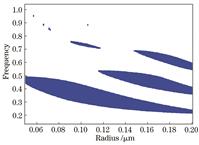
Fig. 1. Fig. 1 Change of the band gap range with the radius of the dielectric cylinder
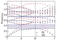
Fig. 2. Fig. 2 Band structure of the complete two-dimensional photonic crystal
Fig. 3. Principle of the resonant coupling unit
Fig. 4. Transmittance distribution at the output
Fig. 5. Influence of the radius of the dielectric cylinder in the microcavity on the transmittance
Fig. 6. Influence of the radius of the medium cylinder outside the microcavity on the transmittance
Fig. 7. Influence of the radius of the dielectric cylinder at the output end on the transmittance
Fig. 8. Schematic diagram of the six-channel wavelength division multiplexer
Fig. 9. Transmittance distribution diagram of the six-channel wavelength division multiplexer
Fig. 10. Field distribution diagram of the wavelength division multiplexer under the corresponding wavelength excitation source. (a) 1.3298 μm; (b) 1.4316 μm; (c) 1.4419 μm; (d) 1.5564 μm; (e) 1.5966 μm; (f) 1.6191 μm
|
Table 1. Parameters of six-channel wavelength division multiplexer
|
Table 2. Crosstalk between channels
|
Table 3. Comparison of different schemes

Set citation alerts for the article
Please enter your email address
© Copyright 2018-2021 | Chinese Laser Press. All Rights Reserved 沪ICP备15018463号-20