
Weifeng Du, Yanqing Wang, Xunjiang Zheng, Wenjie Gao, Tingan Xie. Design and Verification of Stray Light Suppression for Star Sensor[J]. Acta Optica Sinica, 2023, 43(6): 0623001
- Acta Optica Sinica
- Vol. 43, Issue 6, 0623001 (2023)
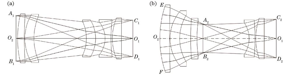
Fig. 1. Schematic of aperture stop matching. (a) Aperture stop is set in front of the light path; (b) aperture stop is set in middle of the light path
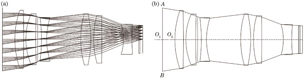
Fig. 2. Design basis of exit pupil aperture of baffle. (a) Derived model of lens; (b) exit pupil aperture of baffle
Fig. 3. Scattering of the part of light blocking ring facing the lens. (a) Scattering path of the part of light blocking ring facing the lens; (b) circular superposition at the phase of detector passing through the lens
Fig. 4. Relationship curves between
Fig. 5. Schematic of envelope size of baffle
Fig. 6. Initial structure of baffle
Fig. 7. Diagram of light blocking rings at bevel angle and right angle. (a) Light blocking rings at bevel angle; (b) light blocking rings at right angle
Fig. 8. Diagram of single scattering at cutting edge
Fig. 9. Discrepancy of scattering energy of image plane caused by different edge thickness. (a) Edge scattering of test baffle 1; (b) edge scattering of test baffle 2; (c) image plane gray caused by edge scattering of test baffle 1; (d) image plane gray caused by edge scattering of test baffle 2
Fig. 10. Design diagram of secondary baffle
Fig. 11. Simulation results of edge thickness and stray illumination
Fig. 12. Stray light test data. (a) Stray light test site diagram; (b) gray level image of stray light on image plane of star sensor; (c) superposition of stray light gray-scale image and sixth-magnitude stars gray level image in different fields of view
Fig. 13. Test data of outfield. (a) Accuracy of star sensor without stray light; (b) accuracy of star sensor interfered by stray light using regular baffle; (c) accuracy of star sensor interfered by stray light using the proposed baffle
|
Table 1. Design input and technical requirements
|
Table 2. Simulation conditions
|
Table 3. Requirements of experimental conditions and techniques

Set citation alerts for the article
Please enter your email address
© Copyright 2018-2021 | Chinese Laser Press. All Rights Reserved 沪ICP备15018463号-20