• Journal of Infrared and Millimeter Waves
  • Vol. 40, Issue 6, 834 (2021)
Yan LUO, Yong-Qin HAO*, and Chang-Ling YAN
Author Affiliations
  • National Key Lab of High-Power Semiconductor Lasers,Changchun University of Science and Technology,Changchun 130022,China
  • show less
    DOI: 10.11972/j.issn.1001-9014.2021.06.018 Cite this Article
    Yan LUO, Yong-Qin HAO, Chang-Ling YAN. Design of high refractive index contrast subwavelength grating reflector for 940 nmVCSEL[J]. Journal of Infrared and Millimeter Waves, 2021, 40(6): 834 Copy Citation Text show less
    Schematic diagram of HCG
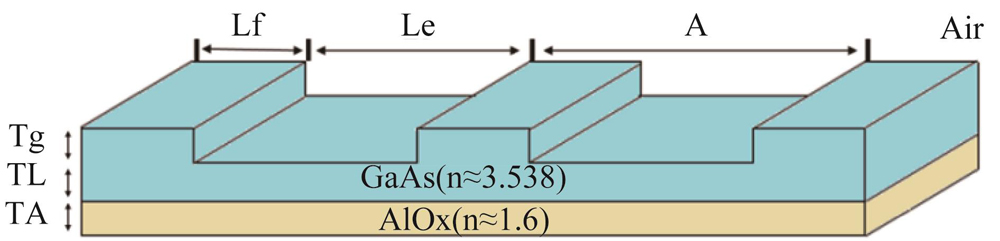
    Fig. 1. Schematic diagram of HCG
    Reflectance of different grating parameters versus wavelength in TE mode (a) grating period, (b) fill factor, (c) grating thickness, (d) stress buffer layer thickness
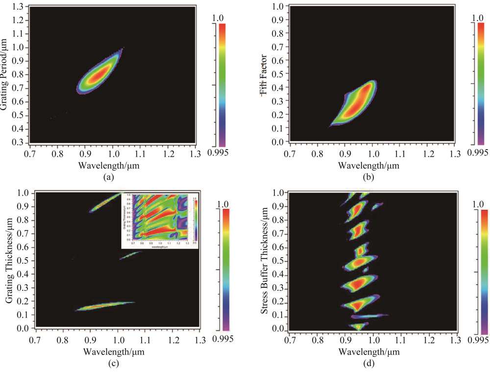
    Fig. 2. Reflectance of different grating parameters versus wavelength in TE mode (a) grating period, (b) fill factor, (c) grating thickness, (d) stress buffer layer thickness
    Reflectivity as function of low refractive index sub-layer thickness and wavelength in TE mode
    Fig. 3. Reflectivity as function of low refractive index sub-layer thickness and wavelength in TE mode
    (a)Reflectivity spectrum of TE-HCG(Λ= 0. 781 μm,f = 0.254,Tg= 0. 166 μm,TL=0. 189 μm,TA=0. 17 μm),(b)Reflectivity spectrum of TM-HCG(Λ= 0. 416 μm,f = 0.618,Tg= 0. 242 μm,TL=0. 109μm,TA=0. 175μm)
    Fig. 4. (a)Reflectivity spectrum of TE-HCG(Λ= 0. 781 μm,f = 0.254,Tg= 0. 166 μm,TL=0. 189 μm,TA=0. 17 μm),(b)Reflectivity spectrum of TM-HCG(Λ= 0. 416 μm,f = 0.618,Tg= 0. 242 μm,TL=0. 109μm,TA=0. 175μm)
    The reflectivity spectrum of TE-HCG and the fill factor difference between the upper and lower gratings is 5%,10% and 15%
    Fig. 5. The reflectivity spectrum of TE-HCG and the fill factor difference between the upper and lower gratings is 5%,10% and 15%
    The reflectivity spectrum of TM-HCG and the fill factor difference between the upper and lower gratings is 5%,10% and 15%
    Fig. 6. The reflectivity spectrum of TM-HCG and the fill factor difference between the upper and lower gratings is 5%,10% and 15%
    ParameterTolerances for RTE>99.5% at λ0Tolerances for RTM>99.5% at λ0
    Tg150~182 nm213~269 nm
    TL132~221 nm88~127 nm
    TA140~220 nm130~185 nm
    Λ702~870 nm376~467 nm
    F17.5~38.6%56.5~66.8%
    Table 1. Optimal range of parameters for TE and TM
    Yan LUO, Yong-Qin HAO, Chang-Ling YAN. Design of high refractive index contrast subwavelength grating reflector for 940 nmVCSEL[J]. Journal of Infrared and Millimeter Waves, 2021, 40(6): 834
    Download Citation