• Advanced Photonics
  • Vol. 1, Issue 1, 014001 (2019)
Jingjing Zhang1, John B. Pendry2、*, and Yu Luo1、*
Author Affiliations
  • 1Nanyang Technological University, School of Electrical and Electronic Engineering, Singapore
  • 2Imperial College London, Blackett Laboratory, Department of Physics, London, United Kingdom
  • show less
    DOI: 10.1117/1.AP.1.1.014001 Cite this Article Set citation alerts
    Jingjing Zhang, John B. Pendry, Yu Luo. Transformation optics from macroscopic to nanoscale regimes: a review[J]. Advanced Photonics, 2019, 1(1): 014001 Copy Citation Text show less
    A simple coordinate transformation that compresses a space along the x axis. As a result, light follows a distorted trajectory, as shown by the red solid line, but emerges from the compressed region traveling in exactly the same direction with the same phase as before. We can predict the metamaterial properties in the brown region that would realize this trajectory for a light ray. Figure reprinted with permission: Ref. 9, © 2010 by the Imperial College London.
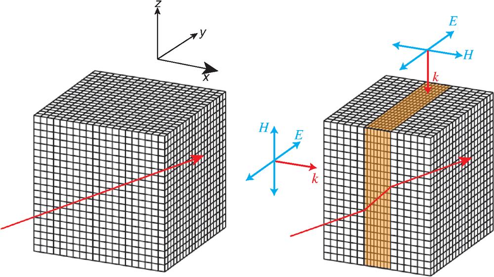
    Fig. 1. A simple coordinate transformation that compresses a space along the x axis. As a result, light follows a distorted trajectory, as shown by the red solid line, but emerges from the compressed region traveling in exactly the same direction with the same phase as before. We can predict the metamaterial properties in the brown region that would realize this trajectory for a light ray. Figure reprinted with permission: Ref. 9, © 2010 by the Imperial College London.
    (a) The undistorted coordinate system, where a ray of light in free space travels in a straight line. (b) The coordinates are transformed to exclude the cloaked region. Trajectories of rays are pinned to the coordinate mesh and therefore avoid the cloaked region, returning to their original path after passing through the cloak. (c) The coordinates are transformed to fold the space into the annulus region. (d) The field distribution for a cloak under the Gaussian beam illumination. (e) The field distribution for a concentration under the Gaussian beam illumination.
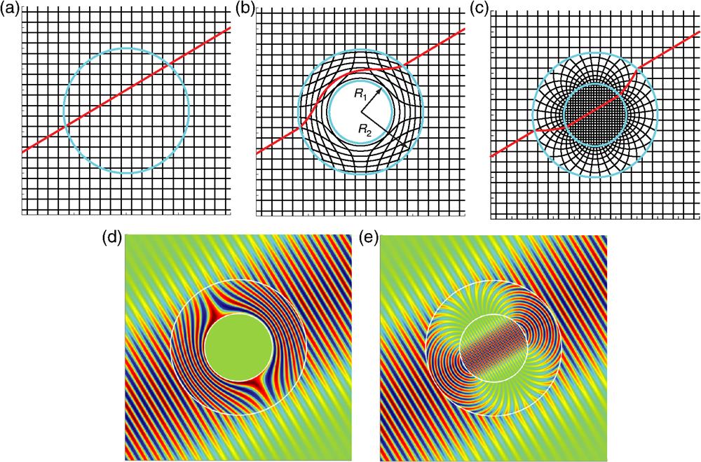
    Fig. 2. (a) The undistorted coordinate system, where a ray of light in free space travels in a straight line. (b) The coordinates are transformed to exclude the cloaked region. Trajectories of rays are pinned to the coordinate mesh and therefore avoid the cloaked region, returning to their original path after passing through the cloak. (c) The coordinates are transformed to fold the space into the annulus region. (d) The field distribution for a cloak under the Gaussian beam illumination. (e) The field distribution for a concentration under the Gaussian beam illumination.
    A carpet cloak designed with quasi-conformal mapping. (a) n2 profile of the cloak. (b) Ez distribution with the cloak located within the rectangle in dashed line when a Gaussian beam is launched at 45 deg toward the ground plane. (c) The reflected ray from the bump of the carpet cloak has been shifted toward the incident point. Figure reprinted with permission: (a) and (b) Ref. 40, © 2008 by the American Physical Society (APS); (c) Ref. 41, © 2010 by APS.
    Fig. 3. A carpet cloak designed with quasi-conformal mapping. (a) n2 profile of the cloak. (b) Ez distribution with the cloak located within the rectangle in dashed line when a Gaussian beam is launched at 45 deg toward the ground plane. (c) The reflected ray from the bump of the carpet cloak has been shifted toward the incident point. Figure reprinted with permission: (a) and (b) Ref. 40, © 2008 by the American Physical Society (APS); (c) Ref. 41, © 2010 by APS.
    A linear transformation that transforms an arbitrary triangular region to another one in the physical space.
    Fig. 4. A linear transformation that transforms an arbitrary triangular region to another one in the physical space.
    (a) The linear transformation for the design of a carpet cloak. (b) Full-wave simulation of Hz profiles with an incident beam at 45 deg to the homogeneous carpet cloak. Figure reprinted with permission: (b) Ref. 51, © 2009 by IEEE.
    Fig. 5. (a) The linear transformation for the design of a carpet cloak. (b) Full-wave simulation of Hz profiles with an incident beam at 45 deg to the homogeneous carpet cloak. Figure reprinted with permission: (b) Ref. 51, © 2009 by IEEE.
    Schematic of the conformal transformation that maps canonical plasmonic systems to singular structures. (a) A thin metal slab that couples to a 2-D line dipole is transformed to a crescent-shaped nanocylinder illuminated by a uniform electric field. (b) Two semi-infinite metal slabs separated by a thin dielectric film that are excited by a 2-D dipole source are transformed to two touching metallic nanowires illuminated by a uniform electric field.
    Fig. 6. Schematic of the conformal transformation that maps canonical plasmonic systems to singular structures. (a) A thin metal slab that couples to a 2-D line dipole is transformed to a crescent-shaped nanocylinder illuminated by a uniform electric field. (b) Two semi-infinite metal slabs separated by a thin dielectric film that are excited by a 2-D dipole source are transformed to two touching metallic nanowires illuminated by a uniform electric field.
    Absorption cross section as a fraction of the physical cross section as a function of frequency for different shapes of (a) crescents and (b) touching nanowires. The absorption spectrum of one individual cylinder is also shown for comparison. (c) The normalized electric field Ex/E0 plotted along the surface of the (a) crescents and (b) touching nanowires at a frequency of 664 THz (where εm=−7.02+0.25i). Here the angle θ is defined in the inset.
    Fig. 7. Absorption cross section as a fraction of the physical cross section as a function of frequency for different shapes of (a) crescents and (b) touching nanowires. The absorption spectrum of one individual cylinder is also shown for comparison. (c) The normalized electric field Ex/E0 plotted along the surface of the (a) crescents and (b) touching nanowires at a frequency of 664 THz (where εm=7.02+0.25i). Here the angle θ is defined in the inset.
    The original plasmonic systems are truncated periodic metallo-dielectric structures depicted in (a), (c), (e), and (g), where the EM source is an array of line dipoles (red arrows), aligned along the y axis, with a pitch of 2π. Under the transformation, the structures shown in (a), (c), (e), and (g) are mapped to a (b) metal groove, (d) metal wedge, (f) pair of overlapping nanowires, and (h) a crescent-shaped nanocylinder, respectively. The source of the line dipole array is transformed into a uniform electric field.
    Fig. 8. The original plasmonic systems are truncated periodic metallo-dielectric structures depicted in (a), (c), (e), and (g), where the EM source is an array of line dipoles (red arrows), aligned along the y axis, with a pitch of 2π. Under the transformation, the structures shown in (a), (c), (e), and (g) are mapped to a (b) metal groove, (d) metal wedge, (f) pair of overlapping nanowires, and (h) a crescent-shaped nanocylinder, respectively. The source of the line dipole array is transformed into a uniform electric field.
    Absorption spectrum as a function of the frequency and the bluntness. Figure reprinted with permission: Ref. 83, © 2012 by APS.
    Fig. 9. Absorption spectrum as a function of the frequency and the bluntness. Figure reprinted with permission: Ref. 83, © 2012 by APS.
    Conformal transformation of a metal-vacuum-metal geometry into a nanowire dimer with (a) local82" target="_self" style="display: inline;">82 and (b) nonlocal88" target="_self" style="display: inline;">88 treatments. Absorption cross-section of 10-nm radius Ag nanowire dimers versus frequency and gap size in (c) local and (d) nonlocal cases.
    Fig. 10. Conformal transformation of a metal-vacuum-metal geometry into a nanowire dimer with (a) local82 and (b) nonlocal88 treatments. Absorption cross-section of 10-nm radius Ag nanowire dimers versus frequency and gap size in (c) local and (d) nonlocal cases.
    (a) Electric field enhancements in the vicinity of the touching point at different degrees of nonlocality β=2πc×10−4 (blue line), β=2πc×10−3 (green line), and β=2πc×10−2 (red line). Solid and dot lines correspond to the analytical and numerical calculations. Gray line plots the field enhancement under local description. (b) Electric field enhancement at the touching point of two nanowires versus frequency and nanowire radius. Figure reprinted with permission: Ref. 89, © 2012 by APS.
    Fig. 11. (a) Electric field enhancements in the vicinity of the touching point at different degrees of nonlocality β=2πc×104 (blue line), β=2πc×103 (green line), and β=2πc×102 (red line). Solid and dot lines correspond to the analytical and numerical calculations. Gray line plots the field enhancement under local description. (b) Electric field enhancement at the touching point of two nanowires versus frequency and nanowire radius. Figure reprinted with permission: Ref. 89, © 2012 by APS.
    The 3-D inversion that maps a metal-dielectric-metal annulus geometry into a pair of nanospheres separated by a small gap.
    Fig. 12. The 3-D inversion that maps a metal-dielectric-metal annulus geometry into a pair of nanospheres separated by a small gap.
    Resonance frequencies of (a) plasmonic modes and (b) Casimir energy versus the separation between two 5-nm-radius gold spheres. Figure reprinted with permission: Ref. 101, © 2013 by the National Academy of Sciences of the United States of America.
    Fig. 13. Resonance frequencies of (a) plasmonic modes and (b) Casimir energy versus the separation between two 5-nm-radius gold spheres. Figure reprinted with permission: Ref. 101, © 2013 by the National Academy of Sciences of the United States of America.
    A conformal transformation compacts (a) the x dimension of a metallodielectric structure into (b) periodic singularities of a plasmonic metasurface. Dispersion of the singular plasmonic metasurface with respect to (c) both the hidden and Bloch wave vectors, (d) the hidden vector alone. Figure reprinted with permission: Ref. 113, © 2017 by the American Association for the Advancement of Science.
    Fig. 14. A conformal transformation compacts (a) the x dimension of a metallodielectric structure into (b) periodic singularities of a plasmonic metasurface. Dispersion of the singular plasmonic metasurface with respect to (c) both the hidden and Bloch wave vectors, (d) the hidden vector alone. Figure reprinted with permission: Ref. 113, © 2017 by the American Association for the Advancement of Science.
    (a) Schematic of singular graphene metasurface with periodical conductivity. (b) and (c) Absorption spectra of two singular graphene metasurfaces showing how the plasmonic resonances merge into a continuum with increasing dissipation losses. Figure reprinted with permission: Ref. 115, © 2018 by the American Chemical Society.
    Fig. 15. (a) Schematic of singular graphene metasurface with periodical conductivity. (b) and (c) Absorption spectra of two singular graphene metasurfaces showing how the plasmonic resonances merge into a continuum with increasing dissipation losses. Figure reprinted with permission: Ref. 115, © 2018 by the American Chemical Society.
    Physical quantitiesBefore transformationAfter transformation
    Scalar potentialϕϕ=ϕ
    Charge densityρρ=ρ/det(Λ¯¯)
    Electric fieldE¯[E¯H¯k¯]=(Λ¯¯T)1·[E¯H¯k¯]
    Magnetic fieldH¯
    Wave vectork¯
    Magnetic flux densityB¯[B¯D¯j¯S¯]=Λ¯¯·[B¯D¯j¯S¯]/det(Λ¯¯)
    Electric displacementD¯
    Current densityj¯
    Poynting vectorS¯
    Table 1. Summary of transformations of different physical quantities.
    Jingjing Zhang, John B. Pendry, Yu Luo. Transformation optics from macroscopic to nanoscale regimes: a review[J]. Advanced Photonics, 2019, 1(1): 014001
    Download Citation