Jingjing Zhang, John B. Pendry, Yu Luo, "Transformation optics from macroscopic to nanoscale regimes: a review," Adv. Photon. 1, 014001 (2019)
Copy Citation Text
Transformation optics is a mathematical method that is based on the geometric interpretation of Maxwell’s equations. This technique enables a direct link between a desired electromagnetic (EM) phenomenon and the material response required for its occurrence, providing a powerful and intuitive design tool for the control of EM fields on all length scales. With the unprecedented design flexibility offered by transformation optics (TO), researchers have demonstrated a host of interesting devices, such as invisibility cloaks, field concentrators, and optical illusion devices. Recently, the applications of TO have been extended to the subwavelength scale to study surface plasmon-assisted phenomena, where a general strategy has been suggested to design and study analytically various plasmonic devices and investigate the associated phenomena, such as nonlocal effects, Casimir interactions, and compact dimensions. We review the basic concept of TO and its advances from macroscopic to the nanoscale regimes.
Transformation optics (TO) is an emerging technique for the design of advanced electromagnetic (EM) media. It is based on the concept that Maxwell’s equations can be written in a form-invariant manner under coordinate transformations, such that only the permittivity and permeability tensors are modified.1–3 With the coordinate transformation applied to the constitutive parameters, EM waves in one coordinate system can be described as if propagating in a different one. The geometric interpretation of Maxwell’s equations utilized in the TO approach provides a powerful and intuitive design tool for the manipulation of EM fields on all length scales.
In the past, the form invariance of Maxwell’s equations has been exploited as a computational tool to simplify numerical electrodynamic simulations. In 1996, a transformation from Cartesian to cylindrical coordinates was applied to solve for the modes of an optical fiber with circular cross section.1 This transformation allowed for efficiently solving a cylindrical geometry using a finite-difference computer code implemented in Cartesian coordinates. The TO technique, however, extends well beyond the domain of computational approaches and has gained a great deal of relevance over the past decade in conjunction with the emerging field of metamaterials. Metamaterials are artificially structured media whose effective material parameters can be engineered to have, in principle, any combination of anisotropic electric and magnetic responses,4–8 making them an enabling path for transformation optical structures.
2 Basic Theory
The physical meaning of coordinate transformation can be given as follows. We start from a Cartesian system with a given set of electric and magnetic fields and their associated Poynting vectors. Next, imagine that the coordinates are continuously distorted into a new system. TO was born of the realization that as the system is distorted it carries with it all the associated fields. Hence, to guide the trajectory of light, only a distortion in the underlying coordinate system is needed, automatically taking with it the light ray. Knowledge of the transformation in turn provides the values of and required to steer the light in this way.
Sign up for Advanced Photonics TOC. Get the latest issue of Advanced Photonics delivered right to you!Sign up now
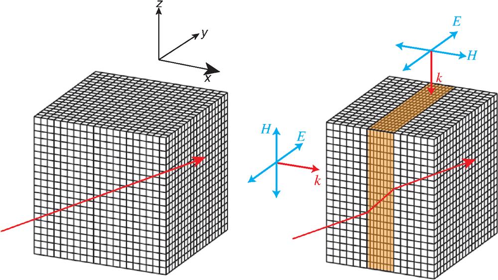
To give an intuitive view of the TO scheme, we consider a very simple distortion of space: a section of the axis is compressed as shown in Fig. 1. To find the values of and that would lead to the ray trajectory given by the red line, we now illuminate the compressed region with test EM waves of two different polarizations (see the right panel).
For a ray propagating along the axis, the condition must hold so that the phase is preserved at the far side of the compressed region. (Here, is the free-space wave vector, is the wave vector in the compressed region, is the compression factor, and is the thickness of the original uncompressed layer.) This condition requires , and thus . Since Maxwell’s equations are symmetrical for and , any transformation must apply equally to these two parameters.2 Therefore, we have
Note that and appear on the same footing because of the symmetry between electric and magnetic fields in the transformed space. For a ray propagating along the axis, since there is no compression in this direction, the refractive index must remain unchanged . Hence, we can deduce
To conclude, if we compress a coordinate system along a certain axis, both and are decreased by the compression factor in the direction of distortion. On the other hand, perpendicular to the direction of distortion, and are increased by the inverse of the compression factor. For a general compression, the formula is applied successively along each of the three axes.
It is possible to follow this intuitive approach of compressing and expanding space to the design of much more complex and functional devices. However, leveraging the formal structure of electromagnetism, we can follow a systematic, general approach that allows the consideration of arbitrary transformations. Under a general spatial operation, EM fields are distorted in a way that is exactly equivalent to a transformation of the electric permittivity and magnetic permeability tensors of the form where () and () are the permittivity (permeability) tensors in the original and transformed space, respectively, and is the Jacobian matrix of the transformation relating differential elements between the primed and unprimed frames. Therefore, we can rewrite Maxwell’s equations in the transformed frame and derive the physical quantities in terms of in the transformed space accordingly. In the new coordinate system, we must use modified values of the permittivity and permeability to ensure that Maxwell’s equations are satisfied. Table 1 summarizes the transformation of different physical quantities in terms of the transformation matrix . Maxwell’s equations thus have the same general form as expected so long as the constitutive parameters and source terms are multiplied by the appropriate factors of the Jacobian matrix and its determinant.
Physical quantities
Before transformation
After transformation
Scalar potential
Charge density
Electric field
Magnetic field
Wave vector
Magnetic flux density
Electric displacement
Current density
Poynting vector
Table 1. Summary of transformations of different physical quantities.
TO has provided a powerful tool for the design of structures capable of controlling the flow of light. The most well-known example is the EM invisibility cloak proposed in 2006.2,10Figure 2(a) shows a ray of light traveling in free space. Suppose we wish to hide the object lying in a spherical region with radius by directing the rays around this region while confining the distorted rays within a larger sphere radius [Fig. 2(b)]. In this way an external observer would be aware neither of the presence of the cloak nor its contents. In other words, any object hidden in the cloak would be invisible to outer observers [see Fig. 2(d)].
Figure 2.(a) The undistorted coordinate system, where a ray of light in free space travels in a straight line. (b) The coordinates are transformed to exclude the cloaked region. Trajectories of rays are pinned to the coordinate mesh and therefore avoid the cloaked region, returning to their original path after passing through the cloak. (c) The coordinates are transformed to fold the space into the annulus region. (d) The field distribution for a cloak under the Gaussian beam illumination. (e) The field distribution for a concentration under the Gaussian beam illumination.
The corresponding space distortion can be realized through the following coordinate transformation:
This transformation compresses the space in the radial direction. Therefore, along the angular coordinates the values of and are increased by the inverse of the compression factor, whereas along the radial direction the values are reduced. The corresponding cloak parameters are
If we take a closer look at the cloak parameters, we find that a spherical cloak is singular on its inner surface, i.e., the values of and either become infinity or zero. To implement such a cloak, it requires that the metamaterials are in general extremely anisotropic and the difficulty of manufacturing such materials increases severely at higher frequencies. Therefore, any practical implementation will always involve a degree of approximation. A two-dimensional (2-D) cylindrical cloak was later proposed as a simplified scheme, and reduced parameters are also suggested to further simplify the design and realization process.11–14 The cylindrical cloak was first demonstrated at microwave frequencies in 2006 using metamaterials,15 followed by a huge surge of attentions from different research groups implementing their own versions of the technology.16–25
Another example of TO device is the electromagnetic field concentrator that can focus the incident electromagnetic waves to the central area and enhance the electromagnetic energy density.26,27 It can be designed by applying the transformation function where the constant stands for the magnification/shrink factor related to the compression/expansion of space. This design gives , . Note that the cloak can be taken as the extreme case where . The incident power is suppressed at the core when and enhanced when . In particular, when , the negative slope of the function gives a folded region where and are negative. In this case, the power that flows through the inner region (core) is larger than that which flows through the whole concentrator, due to the energy circulation between the coating and the inner media, as shown in Fig. 2(e). The device enhances the scattering cross section of an object so that it looks like a scatterer larger than the scale of the whole device.28–30 Space transformation with folded region can also lead to perfect imaging with negative refractive index superlens,31–34 and optical illusion devices that optically cancel the scattering from original objects and restore the optical paths of light to generate illusions.35 The realization of such devices requires layered complex metamaterial structures to achieve the spatially gradient and anisotropic material parameters. Thus, a simplification process is usually taken to reduce the difficulty in designs and fabrications.36–38 Note that devices with extreme-value parameters, including spherical/cylindrical cloaks, superscatterers, superlens, etc., only work within limited frequency band with inevitable absorptions due to the resonant nature of metamaterials.
3 Quasi-Conformal Mapping
To mitigate the material parameter constraints, the flexibility of the coordinate transformations has been explored. Attentions have been turned to the so-called quasi-conformal mapping that allows the design of devices with isotropic dielectric materials or materials with very small anisotropy. As a natural extension from the conformal mapping, the quasi-conformal mapping relaxes the severe restrictions on the conformal mapping while remaining orthogonal such that the permittivity and permeability tensors can be easily realized. These mappings allow for transformations between domains with different conformal modules in two steps. To compensate for the mismatched conformal modules, the virtual domain is first mapped to an intermediate domain with the same conformal module as the physical domain. This can be simply achieved using a uniform compression/expansion , where is the compression/expansion factor. The intermediate domain is then conformally mapped to the physical domain, giving
In contrast to conformal mapping, the material tensors produced by quasi-conformal mapping are not equal to each other due to perturbations to the conformal module, as can be seen from Eq. (7). However, these perturbations are generally small and thus the resulting anisotropy can typically be ignored. In general, this technique does not have a closed form analytical solution. However, the quasi-conformal map can be approximated by solving Laplace equation on the coordinates.39
One example of quasi-conformal mapping is the design of “carpet cloak,” which provides an alternative form of invisibility cloak.40 Instead of completely hiding objects in a free space, a carpet cloak itself appears as a flat reflecting surface so that the objects and the bump made by the objects underneath the carpet are undetectable by light. The carpet cloak can be designed by transforming a rectangular region in the virtual space to an arbitrary region with a defined curved bottom boundary [see Fig. 3(a)]. To minimize the anisotropy factor, the relative size of the cloaked region has to be very small compared to the size of the whole cloak device. For the case in Fig. 3(a), the anisotropy factor becomes a constant of 1.042, and ranges from 0.68 to 1.96.40 Thus, the anisotropy of the carpet cloak can be neglected. Figure 3(b) shows the distribution when a Gaussian beam is launched at 45 deg toward the ground plane covered by a rectangular carpet cloak with a PEC bottom boundary. The cloak cancels out the original scattering by the bump itself so that it appears as a flat mirror. However, there is an unavoidable lateral shift comparable to the height of the cloaked object in the reflected wave due to the approximations made to the anisotropic parameters, as shown in Fig. 3(c), making the object eventually detectable.41
The material parameters of the carpet cloak are nonsingular and can in principle be realized without the need of resonant features. Furthermore, the isotropic material profile simplifies the fabrication process, making its realization in optical spectrum possible. A number of experimental realizations have been reported, including 2-D and 3-D carpet cloaks working at microwave,42–44 near-infrared,45–48 and visible spectra.49,50 However, in all these realizations, the ratio of the size of the hidden region to that of the cloak is fairly small (normally ), due to the isotropy approximation taken in the quasi-conformal mapping. Furthermore, the spatially gradient material parameters require long design and implementation cycles. Despite these limitations, quasi-conformal mappings still hold great utility in bringing TO designs closer to realization.
4 Linear Transformation
Linear transformation is another type of coordinate transformation used to simplify the device design. In 2-D cases, an arbitrary linear transformation can be described as , , , which transfer a line in the initial coordinate to another one in the physical space. Thus, we can find a unique linear transformation to map an arbitrary triangular region to another one (see Fig. 4). The corresponding permittivity/permeability tensor in the transformed geometry is calculated as which is homogeneous and anisotropic.51,52
Figure 4.A linear transformation that transforms an arbitrary triangular region to another one in the physical space.
Therefore, linear transformation opens the way for the design of a homogeneous carpet cloak by linearly compressing the triangular region along the axis into a polygonal region [see Fig. 5(a)],
In the transformed geometry, the permittivity tensor of the nonmagnetic carpet cloak takes the form of
Consider a transverse-magnetic (TM, magnetic field perpendicular to the cloak device) polarized Gaussian beam incident obliquely upon such a carpet cloak on top of a flat surface. The anisotropic cloak layer guides the beam around the bump, making the output beam propagate in exactly the same way as that reflected from a flat surface, as shown in Fig. 5(b).
The permittivity tensor in Eq. (10) can be diagonalized by rotating the optical axis, and may be realized with natural birefringent crystals53–55 or metamaterials with effective uniaxial material profiles, such as dielectric grating structures.56–59 The experimental demonstration of this kind of carpet cloak has been done in visible spectrum, with the calcite crystal53,54 and in near infrared spectrum, with the silicon grating structure.56 Note that the use of natural crystals enables the realization of optical cloak in macroscopic scale, whereas the metamaterial solution offers more freedom as we can engineer the geometrical parameters, such as the filling factor of the gratings, to achieve anisotropy not found in natural materials. The linear transformation has been further applied to design a unidirectional cloak,60 omnidirectional cloaks,61 and other photonic devices, such as waveguide adapters62–65 and magnifying lens.34
5 Conformal Transformation
Although quasi-conformal mapping and linear transformation make the realization of devices more feasible, the inhomogeneous or anisotropic distributions of permeability and permittivity are still challenging to achieve, especially at optical spectrum. Conformal transformation is a scheme that can completely eliminate the requisite anisotropy of the material parameters, thus it is especially useful in the device design at optical frequencies.
A conformal mapping is an analytic transformation that preserves local angles. If we consider an analytic function in the complex plane with , it must satisfy the Laplace’s equation:
If we make a coordinate transformation , also satisfies the Laplace’s equation in the new coordinate system: provided that the transformation is analytic everywhere in the region under consideration. Hence, in electrostatics, a conformal transformation preserves the potential in each coordinate system:
Moreover, the preservation of local angles ensures that the boundary conditions in the transformed space remain unchanged. Thus, the dielectric constant of each material is also conserved:
Since both the electrostatic potential and the material permittivity are preserved under the 2-D conformal mapping, the delicate design of a metamaterial with a spatial variation in its constitutive parameters is no longer necessary. Thus, conformal transformation not only simplifies the fabrication process but also provides an easy route to engineering the plasmonic properties of the transformed nanostructures. In recent years, optical conformal transformation has been exploited extensively to treat subwavelength fields occurring in plasmonic nanosystems, which are difficult to study analytically with traditional theoretical methods, giving a precise design tool.66–69 By applying transformations to simple plasmonic structures that are well understood but do not have the properties we desire, a variety of complex plasmonic structures, such as sharp edges,70 nearly touching spheres,71 and nonconcentric core-shell structures,72 can be generated and studied analytically through the optical properties of the original simple structures.
5.1 Singular Plasmonic Structures
From traditional concepts, it is usually believed that a metallic structure should have a large physical size (as compared to the wavelength) to allow for a broadband light-harvesting process and a nanoparticle of finite size usually sustains localized surface plasmon resonances at discrete, rather than continuous, frequencies. However, there are exceptions to these rules. Some finite nanostructures containing sharp edges (or corners) can behave like infinite plasmonic systems and show a continuous interaction with light over a broad frequency range.73,74 The theory of TO enables the understanding of the physical mechanism behind this phenomenon. The general strategy starts with a well understood canonical plasmonic system whose analytical description is possible, and then a conformal transformation is applied to deduce the solution for a much more complex geometry. This strategy can explain through the two examples shown in Fig. 6.
Figure 6.Schematic of the conformal transformation that maps canonical plasmonic systems to singular structures. (a) A thin metal slab that couples to a 2-D line dipole is transformed to a crescent-shaped nanocylinder illuminated by a uniform electric field. (b) Two semi-infinite metal slabs separated by a thin dielectric film that are excited by a 2-D dipole source are transformed to two touching metallic nanowires illuminated by a uniform electric field.
A thin slab of metal can support surface plasmon excitations with a lower bound cutoff at the zero frequency and an upper bound cutoff at the surface plasmon frequency. However, the energy is dispersed to infinity and cannot be collected for an efficient light harvesting process. By applying a 2-D inverse transformation, which converts the infinite metal slab in the original space into a crescent-shaped cylinder depicted in Fig. 6(a), a dipole source in addition to the slab is transformed to an incident plane wave, and the induced surface plasmons are now incoming waves focused onto the cusp of the crescent. Another example is shown in Fig. 6(b), where the inverse transformation bridges a plasmonic system consisting of two semi-infinite metal slabs and a pair of touching metallic nanowires. The sharp geometrical features in these nanostructures act as singularities for surface plasmons, causing them to propagate toward the sharp points, slowing down as they progress, but never reaching these sharp points. Consequently, light energy builds up around the singularities. In other words, the transformed geometries can harvest light from infinity and ideally concentrate energy to a nanoscale region around the cusp or touching point.
Detailed calculations show that absorption cross sections for the two geometries depicted in Fig. 6 take the following forms, respectively: for the crescent;75for two touching nanowires.76 Here, is the permittivity of the metal, and denote the inner and outer diameters of the crescent; and correspond to the diameter of the two nanowires.
As shown in Figs. 7(a) and 7(b), which display the absorption cross sections as a function of the physical cross section of the crescent and two touching cylinders, both structures exhibit broadband spectra where the absorption cross section is of the order of the overall physical cross section even for such small particle sizes. This broadband light harvesting behavior results from the fact that the induced surface plasmons propagating along the nanostructure surface are compressed toward the singularity, where the group velocity vanishes and energy accumulates. As a consequence, the wavelength is reduced while the energy is increased by the compression factor, leading to a huge increase in the electric field close to the singularity. As illustrated in Figs. 7(c) and 7(d), the maximum field enhancements induced in the crescent and touching-cylinder configurations reach about 1500 and 15,000, respectively.
Figure 7.Absorption cross section as a fraction of the physical cross section as a function of frequency for different shapes of (a) crescents and (b) touching nanowires. The absorption spectrum of one individual cylinder is also shown for comparison. (c) The normalized electric field plotted along the surface of the (a) crescents and (b) touching nanowires at a frequency of 664 THz (where ). Here the angle is defined in the inset.
Based on this presented approach, an analytical relationship between a canonical metallodielectric system and a variety of singular plasmonic structures, including wedges, crescents, rough surfaces, touching cylinders, etc., has been established.70,75,77–82 Compared with traditional computational methods, this conformal transformation approach does not require the implementation of adaptive meshes around the sharp geometrical boundaries (such as edges or surface protrusions), thereby allowing for a more comprehensive understanding of the strongly localized surface plasmon modes at the singularities. This transformation approach can be generalized to investigate some other complicated plasmonic systems containing singularities and, therefore, may lead to a large number of practical consequences, such as single molecular detection, new generations of sensors, efficient light harvesting, and surface enhanced Raman scattering.
5.2 Plasmonic Nanostructures with Blunt Edges/Corners
In real-world applications, singularities or perfectly sharp boundaries in those structures are unlikely to be realized due to limitations in fabrication techniques and the surface tension of the metal. Therefore, the possibility of quantitatively examining how the edge rounding at the sharp boundary will alter the optical responses has great significance on both theoretical and practical levels. TO enables a systematic investigation of a general class of blunt nanostructures by applying conformal mappings to the truncated metallodielectric system associated with the singular structures.83,84 A number of such examples are displayed in Fig. 8. The analytical studies reveal how the edge rounding of the nanostructures can be engineered to achieve peculiar optical responses including broadband or selective spectral dependence of absorbed and scattered light as well as large local electric field enhancements. Take the blunt crescent geometry shown in Fig. 8(h) as the example. The resonance condition of the localized surface plasmon modes can be deduced from the corresponding slab geometry in Fig. 8(g),83which indicates that the positions of the plasmonic resonances and hence the optical responses of the structure can be controlled by the three geometrical parameters , , and . Properly altering these parameters can tune the frequency and the linewidth of the plasmonic resonances to any predesigned values. Figure 9 shows how the quantized plasmonic modes merge into a continuum when the crescent cusp becomes sharper and sharper. The ability to engineer the physical parameters of metallic nanostructures and thus to maneuver their optical responses provides great promise for the development of new devices and applications. Furthermore, theoretical models can predict unique plasmonic responses of structures that are yet to be fabricated, providing important guidelines for the experiments85–87 and motivating further synthetic work in these areas.
Figure 8.The original plasmonic systems are truncated periodic metallo-dielectric structures depicted in (a), (c), (e), and (g), where the EM source is an array of line dipoles (red arrows), aligned along the axis, with a pitch of . Under the transformation, the structures shown in (a), (c), (e), and (g) are mapped to a (b) metal groove, (d) metal wedge, (f) pair of overlapping nanowires, and (h) a crescent-shaped nanocylinder, respectively. The source of the line dipole array is transformed into a uniform electric field.
In singular structures containing sharp asperities/corners or nearly touching particles, the nonlocal effect, i.e., spatial dispersion in the metal permittivity, plays a key role in the performance of nanodevices, where the classical macroscopic electromagnetism breaks down. An accurate description of optical properties in the subnanometer regime requires the implementation of spatially dispersive permittivities beyond the Drude free electron gas, taking into account the effect of electron–electron interactions. Incorporating nonlocal effects into the TO approach requires the transformation of the permittivity tensor with transverse and longitudinal components under the conformal inversion. The mapping only modifies the longitudinal permittivity according to , yielding a spatially dependent nonlocal parameter (here, is taken as the hydrodynamic parameter, which is proportional to the surface charge thickness according to ). Figures 10(a) and 10(b) show the inversion of a pair of nearly touching nanowires in local and nonlocal cases, respectively. The original uniform charge thickness along the nanowires boundaries maps into a periodic nonuniform width, where the corresponding nonlocal problem can be solved by implementing eikonal approximation.88,89
Figure 10.Conformal transformation of a metal-vacuum-metal geometry into a nanowire dimer with (a) local82 and (b) nonlocal88 treatments. Absorption cross-section of 10-nm radius Ag nanowire dimers versus frequency and gap size in (c) local and (d) nonlocal cases.
A more general strategy for the inclusion of nonlocal effects in the TO frame can be done through a recently developed simplified model for nonlocality.90 This method treats the nonlocality by replacing the spatially dispersive metal with a composite material consisting of a thin virtual dielectric layer located on top of a local metal. The thickness, , and permittivity, , of this layer are designed so that the transmission and reflection coefficients for all incident wave vectors and at all frequencies are the same as in the spatially dispersive metal. This model has been implemented in the TO description of separated nanowires and fully-analytic closed-form expressions for the absorption cross section and field enhancement have been obtained.90Figures 10(c) and 10(d) plot the absorption spectrum of the nanowire dimer in the local and nonlocal cases. As the separation between the two nanowires decreases, the surface plasmon modes in the local case redshift toward zero frequency without bound [see Fig. 10(c)]. In sharp comparison, the nonlocal surface charge screening blueshifts the plasmonic resonances, especially at small separation, setting an upper bound for the resonance shifting. This nonlocal saturation phenomenon has been experimentally confirmed in a number of different plasmonic configurations.91–93
The nonlocal effects also set an ultimate bound for the maximum field enhancements. As shown in Fig. 11(a), the electric field along the surface of touching nanowires dramatically decreases with increased nonlocal screening,89 and the enhancement in the vicinity of the touching point for (corresponding to the realistic nonlocality in silver) is reduced by about 50 times. To maximize the field enhancement, the interplay between the nonlocal and radiative effects must be carefully considered. As shown in Fig. 11(b), small particles exhibit poor enhancement owing to strong nonlocal electron screening, whereas, large particles are affected by pronounced radiative losses and hence show reduced enhancement. The balance of these two effects leads to an optimum choice of the radius between 30 and 80 nm.
5.4 Three-Dimensional Structures and Quantum Fluctuation
TO has been extensively employed in 2-D scenarios to investigate the interaction of light with a number of metal structures70,75,77–84,88,89,94–96 processing translation symmetry (see Refs. 66, 97, and 98 for a review). However, those studies describe only a subset of the spectrum with electric fields perpendicular to the symmetric axis. The extension of the TO framework to 3-D is nontrivial because many plasmonic and quantum-fluctuation-related phenomena require a complete description of the plasmonic modes over the whole spectrum. The difficulty of the 3-D generalization lies in the fact that the permittivity of the transformed material is no longer preserved but acquires a spatial dependence according to under an arbitrary 3-D conformal mapping .71,99 Take the 3-D inversion in Fig. 12 as the example. The transformed annulus geometry has an inhomogeneous permittivity given by where is the permittivity of the metal sphere or background in the physical space. Despite this minor complication, the simplification of geometry still enables us to find a closed-form solution of the electrical potential in the inhomogeneous system,100where represents spherical harmonics; and are expansion coefficients, which can be determined through boundary conditions.
Figure 12.The 3-D inversion that maps a metal-dielectric-metal annulus geometry into a pair of nanospheres separated by a small gap.
The factor in Eq. (19) results from the inhomogeneous permittivity of the annulus geometry. Its presence spoils the spherical symmetry, and as a result, the total angular momentum is no longer conversed. Nevertheless, detailed calculations show that such a minor complication couples the boundary equations only to the neighboring , giving rise to a tridiagonal reflection matrix, which can be solved easily.100 The reflection matrix contains all the necessary information of the modes supported by the system. For instance, the resonance frequencies of the modes can be obtained by setting the determinant of the reflection matrix to zero. Results obtained in this way are plotted in Fig. 13(a), which shows that as the separation between the two metal spheres decreases, the surface plasmon modes factor into bonding and antibonding. The bonding modes (red-dashed lines) redshift to zero frequency with decreasing . On the other hand, the antibonding modes (blue-dashed lines) blueshift as decreases and finally fall into two branches, one below and the other above the surface plasmons frequency. The branch below the surface plasmon frequency is widely discussed in the literature in the contents of plasmonic hybridization,102–105 where the electric fields of these modes are driven out of the gap because of the repulsion of surface charges. In sharp contrast, the branch of modes above the surface plasmon frequency shows a much more interesting behavior. Their mode energy is drawn into the gap despite the repulsion between the charges accumulated on the two particles. Because of their anomalous behavior, these modes are named the anomalous antibonding modes.100 They are rarely investigated in previous studies perhaps because they only exist at extremely small gaps, where traditional approaches, such as multipole scattering, demand too much time to get a convergent result.
As mentioned above, the description of the full set of modes enables us to go beyond the optical responses of the structure to study related phenomena in other fields, such as Casimir forces,106–108 heat transfer,109,110 and quantum friction.111Figure 13(b) displays one such result, where the Casimir energy between two gold spheres is plotted against the gaps between them. Both local112 and nonlocal101 results are presented, which show that the nonlocal screening effects significantly saturate the Casimir energy and hence decrease the force at extremely small separations. The black-dot line corresponds to the calculation using Drude description of metal permittivity. The large deviations between the Drude mode and realistic metal parameters highlight the significant role of bonded electrons in Casimir interactions.101 Apart from the separated metal spheres, the 3-D TO framework described above can be easily extended to other complex plasmonic systems, including 3-D blunt crescents,99 oblate and prolate spheroids,95 etc.
5.5 Compact Dimension in Singular Plasmonic Metasurfaces
As the last example of this review article, we show how to use the TO approach to compress a whole spatial dimension of a 3-D system into a set of singular points of a 2-D metasurface.113
In traditional optical systems, the number of characteristic vectors is normally equal to the dimensionality of the system. To design a plasmonic metasurface with compact dimensions, we start with a 3-D periodically layered metallodielectric stack in Fig. 14(a) and apply a conformal transformation , converting it into a 2-D singular plasmonic surface in Fig. 14(b). The theory of TO shows that the surface plasmon modes supported by the transformed geometry are characterized by three wave vectors despite the 2-D nature of the metasurface.113,114 For instance, the modes propagating along the vertical direction have two characteristic wave vectors [see Fig. 14(c)], i.e., the Bloch wave vector , which characterizes the energy flow between neighboring unit cells, and the hidden wave vector , which characterizes how the surface plasmons propagate toward the singular points. The latter is generally missing in traditional gratings or gradient metasurfaces but plays an important role in the singular plasmonic surface considered here.
To further illustrate the role of the hidden modes, we set . Then, for traditional gradient metasurfaces, surface plasmons have to form standing waves resulting in zero power flow everywhere within a unit cell. On the contrary, the singular metasurface is quite different because the hidden modes still have a nonzero [see Fig. 14(d)]. These modes can propagate toward the singular points without reflection, as shown by the field plot of Fig. 14(b). In other words, the singular points resulting from the compression of an infinite hidden dimension behave like energy sinks, which completely decouple the power flows within and between unit cells.
Singular points associated with compact dimensions can be achieved by a number of ways. Apart from the geometric singularities depicted in Fig. 14(b), a flat graphene sheet with periodically doped conductivity, the values of which are singular at certain points, can also have a hidden dimension.115 Since the continuum of modes associated with a 3-D structure is compressed into a 2-D geometry, the singular metasurface exhibits a number of striking properties that are difficult to achieve with a conventional 2-D plasmonic system. For example, to couple free-space radiation to surface plasmons with traditional methods, the phase matching condition must be carefully considered. In general, at fixed frequencies, the surface modes can be excited only at specific incident angles, whereas at fixed incident angles, the modes can be excited only at discrete frequencies. Nevertheless, the singular metasurfaces no longer have to satisfy such rules. The interplay of Bloch and hidden modes in singular metasurfaces enables broadband wide-angle excitation of surface plasmons. To illustrate this point, Figs. 15(b) and 15(c) plot the absorbance of singular graphene metasurfaces at the normal incidence. The results show that an absorption level around 50% can be achieved over a continuous frequency band of .
Transformational optics offers unprecedented control over the propagation and confinement of electromagnetic fields at both supra- and subwavelength scales. It not only enables the design of a variety of electromagnetic devices such as the invisibility cloaks and illusion devices but also allows the study of plasmonic nanostructures, revealing the key features that optimize light harvesting and plasmonic field enhancement. Taking into account practical factors including geometric bluntness, nonlocal effects, material limitations, etc., brings the TO approach a step forward toward realistic applications. In fact, the range of applicability of this powerful method is beyond the manipulation of electromagnetic waves and description of the optical properties of metals but can be extended to other physical fields, such as acoustic waves,116–118 elastic waves,119–121 matter waves,122 and thermal fields.123,124 The recent breakthrough that shows continuum of modes of the 3-D structure can be directly mapped into the 2-D metasurface, which opens up a brand new direction for the applications of TO. We expect more exciting applications of this methodology and more experimental realizations reported in the future.