Author Affiliations
1Key Laboratory of Infrared System Detection and Imaging Technology, Chinese Academy of Sciences, Shanghai 200083, China2University of Chinese Academy of Sciences, Beijing 100049, China3Shanghai Institute of Technical Physics, Chinese Academy of Sciences, Shanghai 200083, Chinashow less
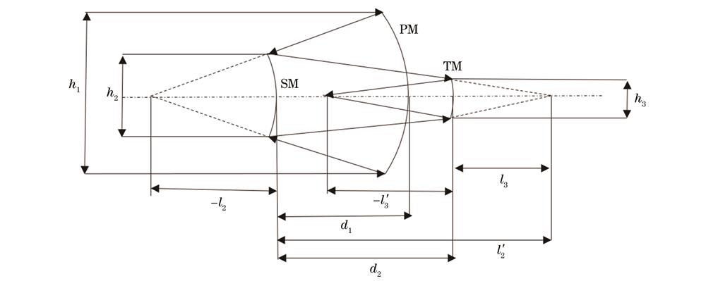
Fig. 1. Initial structure of coaxial three-mirror system
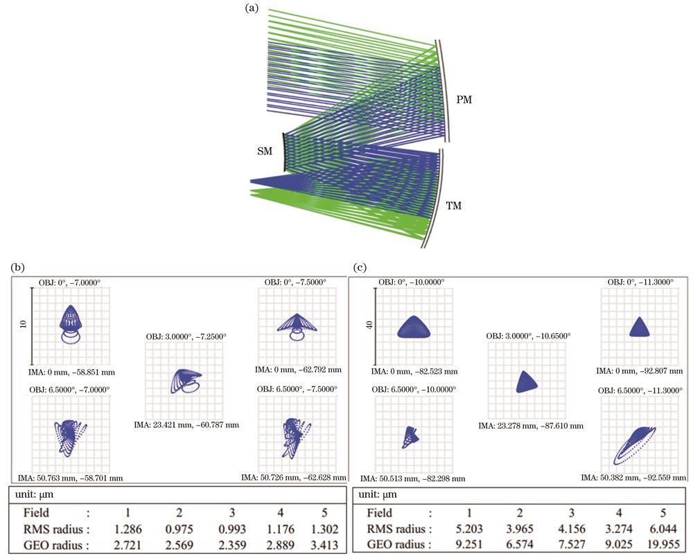
Fig. 2. Design results of off-axis three-mirror system. (a) Optical layout of off-axis three-mirror system; (b) visible and infrared spot diagrams; (c) THz spot diagram
Fig. 3. Design results of VNIR. (a) Optical layout; (b) MTF curves; (c) spot diagram
Fig. 4. Design results of SWIR.(a) Optical layout of SWIR system; (b) MTF curves; (c) spot diagram
Fig. 5. Design results of TIR. (a) Optical layout of TIR system; (b) MTF curves; (c) spot diagram
Fig. 6. Overall diagram of integrated optical system
Band | Central wavelength /μm | Resolution /m | Utilization |
---|
1 | 0.470 | 75 | True color(blue) | 2 | 0.550 | 75 | True color(green) | 3 | 0.650 | 75 | True color(red),optical thickness | 4 | 0.865 | 75 | Optical thickness | 5 | 1.600 | 100 | Optical thickness,effective particle radius | 6 | 2.100 | 100 | Effective particle radius | 7 | 8.000 | 100 | Cloud phase | 8 | 11.000 | 100 | Cloud phase,cloud top temperature,effective particle radius | 9 | 12.000 | 100 | Cloud phase,cloud top temperature,effective particle radius | 10 | 343.250(874 GHz) | 10000 | Ice water path |
|
Table 1. Channel set
Parameter | THz | VNIR | SWIR | TIR |
---|
F number | 3 | 2 | 2 | 2 | Wavelength /μm | 324.680-364.080 [(874±50)GHz] | 0.470-0.865 | 1.600-2.100 | 8.000-12.000 | Input aperture /mm | 150 | 42 | 68 | 68 | IFOV(instantaneous field of view)/mrad | 22.00 | 0.17 | 0.22 | 0.22 |
|
Table 2. Design parameters of system
Tolerance | PM | SM | TM |
---|
x/y decentered tolerance /mm | 0.10 | 0.05 | 0.05 | x/y tilt tolerance /(″) | 30 | 30 | 30 | Radius tolerance /mm | 0.2 | 0.2 | 0.2 | Conical coefficient tolerance | 0.0010 | 0.0010 | 0.0005 | Surface tolerance(λ=632.8 nm) | λ/25 | λ/25 | λ/25 |
|
Table 3. Tolerance of telescope system
Tolerance | PM/ SM/ TM |
---|
x/y decentered tolerance /mm | 0.05 | x/y tilt tolerance /(″) | 30 | Radius tolerance /mm | 0.2 | Conical coefficient tolerance | 0.001 | Surface tolerance(λ=632.8 nm) | λ/25 |
|
Table 4. Tolerance of VNIR optical system
Tolerance | TIR | SWIR |
---|
x/y decentered tolerance /mm | 0.02 | 0.02 | x/y tilt tolerance /(″) | 36 | 36 | Thickness /mm | 0.10 | 0.02 | Radius /fringe | 3 | 3 |
|
Table 5. Tolerance of TIR and SWIR systems
Probability /% | Tolerance |
---|
VNIR | SWIR | TIR |
---|
90 | 0.751 | 0.726 | 0.390 | 50 | 0.860 | 0.812 | 0.433 | 10 | 0.911 | 0.860 | 0.454 |
|
Table 6. Monte-Carlo tolerance analysis results