
Wei Guo, De-Sen Yang. Sound focusing in inhomogeneous waveguides [J]. Acta Physica Sinica, 2020, 69(7): 074301-1
- Acta Physica Sinica
- Vol. 69, Issue 7, 074301-1 (2020)
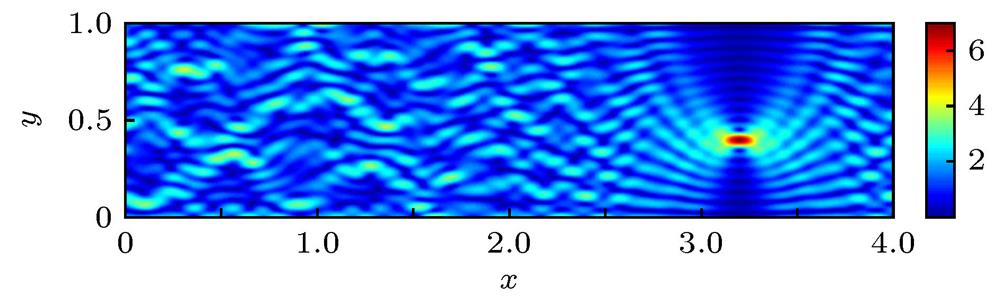
Fig. 1. Sound focusing in homogeneous waveguides.
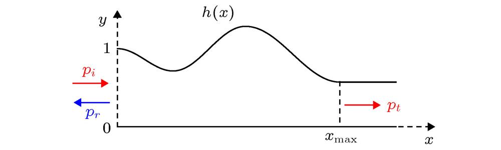
Fig. 2. Configuration of rigid waveguides with varying cross-sections.
Fig. 3. Acoustic focusing field in the waveguide as calculated by the present method. The foci are located at (a)
 (3.2, 0.9) in transmission region and (b)
 in scattering region, respectively. The blue solid lines in (c) and (d) are
 corresponding to (a) and (b), respectively, and the black dotted lines are
 generated by
 (plane wave). The insets plot the modulus of the corresponding incident waves.
(3.2, 0.9) in transmission region and (b)
in scattering region, respectively. The blue solid lines in (c) and (d) are
corresponding to (a) and (b), respectively, and the black dotted lines are
generated by
(plane wave). The insets plot the modulus of the corresponding incident waves. Fig. 4. (a) Sound two-point focusing field in the waveguide with varying cross-section, the foci are located at
 and
and
 ; (b) modulus of the optimal incident pressure; (c) the blue solid line represents
 in (a); the red dot-dashed line shows
 when the wave focus only at
 , which is same as the blue solid line in
 Fig. 3(c) ; and the black dashed line shows
 when the wave focus only at
 . The frequency and geometries of the waveguide are same as
 Fig. 3 .
and
; (b) modulus of the optimal incident pressure; (c) the blue solid line represents
in (a); the red dot-dashed line shows
when the wave focus only at
, which is same as the blue solid line in when the wave focus only at
. The frequency and geometries of the waveguide are same as Fig. 5. Configuration of rigid waveguides involving a scatterer.
Fig. 6. (a) Sound focusing field in the waveguide with a scatterer. The focus is located at
 ; (b) sound field generated by a plane wave
 ; (c) modulus of the pressure of optimal incident wave in (a) and that of the plane incident wave in (b); (d)
 in (a) (blue solid line) and (b) (black dotted line).
; (b) sound field generated by a plane wave
; (c) modulus of the pressure of optimal incident wave in (a) and that of the plane incident wave in (b); (d)
in (a) (blue solid line) and (b) (black dotted line). Fig. 7. (a) Sound focusing field in the waveguide with negative sound-speed gradient and a scatterer. The focus is located at
 , where
 is the depth; (b)the sound speed profile; (c)
 (blue solid line) compared with that generated by
 . The insetplotsthe modulus of the optimal incident pressure (blue solid line) and
 (black dashed line).
, where
is the depth; (b)the sound speed profile; (c)
(blue solid line) compared with that generated by
. The insetplotsthe modulus of the optimal incident pressure (blue solid line) and
(black dashed line). Fig. 8. Sound focusing fields when the optimal incident wave is discretized: (a) Half-wavelength spacing; (b) single-wavelength spacing; (c) the moduli of the two spaced incident waves; (d) the red dashed line and the black dot-dashed line are the corresponding
 generated by the incident waves in (c). The blue solid line is the theoretical result which is same as that in
 Fig. 3(c) .
generated by the incident waves in (c). The blue solid line is the theoretical result which is same as that in Fig. 9. Sound focusing fields when (a) the moduli and (b) the arguments of the optimal incident wave are perturbed; (c) the red dashed line is the incident wave with perturbed moduli, and the black dot-dashed line is that with perturbed arguments; (d) the red dashed line and the black dot-dashed line are the corresponding
 generated by the incident waves in (c). The blue solid line is the result without perturbation which is same as that in
 Fig. 3(c) .
generated by the incident waves in (c). The blue solid line is the result without perturbation which is same as that in 
Set citation alerts for the article
Please enter your email address
© Copyright 2018-2021 | Chinese Laser Press. All Rights Reserved 沪ICP备15018463号-20