
Daewook Kim, Xiaolong Ke, Weslin Pullen, Tianyi Wang, Heejoo Choi, Vipender Singh Negi, Lei Huang, Mourad Idir. Generalized large optics fabrication multiplexing[J]. Journal of the European Optical Society-Rapid Publications, 2022, 18(1): 2022002
Journals >Journal of the European Optical Society-Rapid Publications >Volume 18 >Issue 1 >Page 2022002 > Article
- Journal of the European Optical Society-Rapid Publications
- Vol. 18, Issue 1, 2022002 (2022)
![The 8.4 m-class large polishing machine (LPM) with dual tool configuration at the University of Arizona is shown on the left. The middle figure shows an example surface error map of a synthetic 8.4 m diameter mirror with two tool feed modes: (a) “in–out” and (b) “in–in” feed modes for the multiplexed dual-tool polishing case [12].](/richHtml/JEOS-RP/2022/18/1/2022002/2022002-fig1.jpg)
Fig. 1. The 8.4 m-class large polishing machine (LPM) with dual tool configuration at the University of Arizona is shown on the left. The middle figure shows an example surface error map of a synthetic 8.4 m diameter mirror with two tool feed modes: (a) “in–out” and (b) “in–in” feed modes for the multiplexed dual-tool polishing case [12].
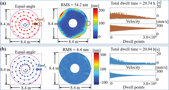
Fig. 2. CCOS benchmark case study showing the final surface error map and the time evolution of the CCOS run parameters through two sequential single-tool runs using (a) Tool1 and (b) Tool2.
Fig. 3. Dual-tool multiplexing simulation tool path (left), final surface error map (middle), and the time evolution of the CCOS run parameters (right) for two-tool feed modes: (a) “in–in” feed mode and (b) “in–out” feed mode.
Fig. 4. The top two rows show differential surface error maps at different progressive time instances obtained using the multi-tool multiplexing simulation (cumulated total dwell time runs from 1 through 6, note the changing scalebar), bringing down the initial (i.e., total dwell time = 0 h) surface figure error of 2210 nm RMS to 7.9 nm RMS using four tools simultaneously. The bottom row shows the tool path (left), final surface error map (middle), and time evolution of the CCOS run parameters (right).

Set citation alerts for the article
Please enter your email address
© Copyright 2018-2021 | Chinese Laser Press. All Rights Reserved 沪ICP备15018463号-20