• Journal of the European Optical Society-Rapid Publications
  • Vol. 18, Issue 1, 2022002 (2022)
Daewook Kim1、2、3、*, Xiaolong Ke4, Weslin Pullen1, Tianyi Wang5, Heejoo Choi1、3, Vipender Singh Negi6, Lei Huang5, and Mourad Idir5
Author Affiliations
  • 1James C. Wyant College of Optical Sciences, The University of Arizona, 1630 E. University Blvd., Tucson, AZ 85721, USA
  • 2Department of Astronomy and Steward Observatory, Univ. of Arizona, 933 N. Cherry Ave., Tucson, AZ 85721, USA
  • 3Large Binocular Telescope Observatory, Univ. of Arizona, Tucson, AZ 85721, USA
  • 4School of Mechanical and Automotive Engineering, Xiamen University of Technology, Xiamen 361024, China
  • 5National Synchrotron Light Source II (NSLS-II), Brookhaven National Laboratory, PO Box 5000, Upton, NY 11973, USA
  • 6Academy of Scientific and Innovative Research (AcSIR), Ghaziabad 201002, India
  • show less
    DOI: 10.1051/jeos/2022002 Cite this Article
    Daewook Kim, Xiaolong Ke, Weslin Pullen, Tianyi Wang, Heejoo Choi, Vipender Singh Negi, Lei Huang, Mourad Idir. Generalized large optics fabrication multiplexing[J]. Journal of the European Optical Society-Rapid Publications, 2022, 18(1): 2022002 Copy Citation Text show less

    Abstract

    High precision astronomical optics are manufactured through deterministic computer controlled optical surfacing processes, such as subaperture small tool polishing, magnetorheological finishing, bonnet tool polishing, and ion beam figuring. Due to the small tool size and the corresponding tool influence function, large optics fabrication is a highly time-consuming process. The framework of multiplexed figuring runs for the simultaneous use of two or more tools is presented. This multiplexing process increases the manufacturing efficiency and reduces the overall cost using parallelized subaperture tools.High precision astronomical optics are manufactured through deterministic computer controlled optical surfacing processes, such as subaperture small tool polishing, magnetorheological finishing, bonnet tool polishing, and ion beam figuring. Due to the small tool size and the corresponding tool influence function, large optics fabrication is a highly time-consuming process. The framework of multiplexed figuring runs for the simultaneous use of two or more tools is presented. This multiplexing process increases the manufacturing efficiency and reduces the overall cost using parallelized subaperture tools.

    1 Introduction

    Large astronomical optics computer controlled optical surfacing (CCOS) processes require a vast workforce and financial resources [17]. Increasing the material (e.g., glass, ceramics, SiC mirror substrates) removal rate and minimizing dwell time have been the two common approaches for reducing the overall processing time [811]. As an innovative breakthrough, we introduced the concept that the CCOS efficiency can be improved when multiple tools are multiplexed [12]. This helps reduce the fabrication process time while gradually correcting the surface using multiple tools simultaneously to enhance the quality of the surface. An additional advantage is correcting the surface error using different tool-workpiece contact-size tools to target different spatial frequency errors. We summarize the fundamental concept of multiplexing in Section 2 and present a generalized multi-tool multiplexing model which merges more than two dwell time maps and optimizes multiple polishing tools run parameters in Section 3.

    2 Multiplexed dual-tool computer controlled optical surfacing

    The efficiency of the optics manufacturing process can be significantly improved with multiple fabrication tools by adopting a simultaneous CCOS multiplexing process [8] based on the mathematical dwell time treatment and multiplexing framework described by Ke et al. [12]. The 8.4 m class large polishing machine (LPM) at the Richard F. Caris Mirror Lab, University of Arizona, consists of two tools with different sizes, as shown in Figure 1 (left).

    The 8.4 m-class large polishing machine (LPM) with dual tool configuration at the University of Arizona is shown on the left. The middle figure shows an example surface error map of a synthetic 8.4 m diameter mirror with two tool feed modes: (a) “in–out” and (b) “in–in” feed modes for the multiplexed dual-tool polishing case [12].

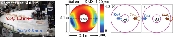
    Figure 1.The 8.4 m-class large polishing machine (LPM) with dual tool configuration at the University of Arizona is shown on the left. The middle figure shows an example surface error map of a synthetic 8.4 m diameter mirror with two tool feed modes: (a) “in–out” and (b) “in–in” feed modes for the multiplexed dual-tool polishing case [12].

    A 1.2 m diameter stressed lap (the top tool in Fig. 1 left) and a 0.3 m diameter non-Newtonian lap (the bottom tool in Fig. 1 left) were used in the LPM to ensure adequate removal for the Large Synoptic Survey Telescope (renamed as Vera C. Rubin Observatory) and Giant Magellan Telescope (GMT). Both tools can be concurrently controlled during a single CCOS run. As another possible machine configuration, two or more robotic arm polishers can be installed surrounding the unit under fabrication (UUF) to enable a simultaneous operation of multiple tools or fabrication processes.

    Figure 1 (middle) shows the simulated initial surface error map with 1.76 μm RMS (root mean square) for multiplexed CCOS case studies. As a side note, large aspheric optical surface error maps are often measured by computer generated hologram interferometry or deflectometry. Two tools can be fed in two possible modes for the dual-tool (i.e., two concurrent tools) multiplexing case using the Rho (ρ) machine axis along the mirror radial direction. One is the “in–out” mode, and the other is the “in–in” mode. These two-tool feed modes apply to most dual-tool polishing scenarios, especially with a gantry-type polishing machine structure. In the “in–out” method (see Fig. 1a), Tool1 and Tool2 move in the same direction so that tool collision can be avoided. Primarily, when polishing a mirror with a central obscuration, the “in–in” feed mode (see Fig. 1b) can be used because tool collision is automatically prevented due to the obscuration.

    As a benchmark, a traditional (i.e., non-multiplexed), sequential two-tool run case is simulated in Figure 2. Figure 2a shows that the surface figure error is reduced from 1.76 μm to 54.2 nm RMS after figuring with Tool1. The residual figure error is further processed using Tool2 (see Fig. 2b), and the final residual error is 4.4 nm RMS. The total dwell time is 20.74 h + 20.04 h = 40.78 h (hours).

    CCOS benchmark case study showing the final surface error map and the time evolution of the CCOS run parameters through two sequential single-tool runs using (a) Tool1 and (b) Tool2.

    Figure 2.CCOS benchmark case study showing the final surface error map and the time evolution of the CCOS run parameters through two sequential single-tool runs using (a) Tool1 and (b) Tool2.

    In the dual-tool multiplexed case, Tool1 is selected as the primary tool so that the run parameters of Tool2 (i.e., dwell time and velocity) are adjusted and synchronized with the primary tool [12]. The dwell time calculated for each tool is synched in real-time. Specifically, the velocity adjustment algorithm [12] has adjusted the velocities for Tool1 and Tool2 to be within their respective maximum speed. Also, appropriate tool paths for the multi-tool scenario are carefully studied. The performances of the “in–in” and the “in–out” feed modes are compared in Figures 3a and 3b. Both feed modes achieve the same final error of 4.3 nm RMS.

    Dual-tool multiplexing simulation tool path (left), final surface error map (middle), and the time evolution of the CCOS run parameters (right) for two-tool feed modes: (a) “in–in” feed mode and (b) “in–out” feed mode.

    Figure 3.Dual-tool multiplexing simulation tool path (left), final surface error map (middle), and the time evolution of the CCOS run parameters (right) for two-tool feed modes: (a) “in–in” feed mode and (b) “in–out” feed mode.

    The “in–in” tool feed mode shows a shorter dwell time (21.55 h) than the “in–out” feed mode (25.20 h). Also, when the “in–in” feed mode is used (see Fig. 3a), the density of the dwell points increases as the tools move toward the center of the UUF and the dwell time distributed to each dwell point becomes shorter.

    Compared with the total 40.78 h two sequential single-tool runs (Fig. 2), the dual-tool multiplexed case (Fig. 3) time efficiency is significantly higher (i.e., about 2×) while it achieves a similar final surface shape accuracy within the numerical simulation accuracy (i.e., 4.3 nm RMS in Fig. 3 compared to 4.4 nm RMS in Fig. 2).

    3 Generalized multiplexing of concurrent tools

    The CCOS multiplexing process [12] can be readily extended and generalized to more than two tools removing the target error map concurrently. The machine axis utilized to drive multiple tools will be determined by the available CCOS machine configuration. For instance, two tools can be driven using the Rho axis while the other two tools can be controlled using robot-arm polishers. All tools may even run on the UUF as independent polishing modules (e.g., wired or wireless polisher units) following the multiplexed dwell time tool path and schedules. An example of a different initial surface error map (top-left error map with 2210 nm RMS in Fig. 4) using four multiplexed tools placed with a phase interval of 90° along the coordinate axes is presented in Figure 4. The 8.4 m UUF rotates counter-clockwise while all four tools simultaneously move inward (radially). This case study shows the total run time of 32.20 h to successfully decrease the figure error of 2210 nm RMS to 7.9 nm RMS in a single multiplexed run.

    The top two rows show differential surface error maps at different progressive time instances obtained using the multi-tool multiplexing simulation (cumulated total dwell time runs from 1 through 6, note the changing scalebar), bringing down the initial (i.e., total dwell time = 0 h) surface figure error of 2210 nm RMS to 7.9 nm RMS using four tools simultaneously. The bottom row shows the tool path (left), final surface error map (middle), and time evolution of the CCOS run parameters (right).

    Figure 4.The top two rows show differential surface error maps at different progressive time instances obtained using the multi-tool multiplexing simulation (cumulated total dwell time runs from 1 through 6, note the changing scalebar), bringing down the initial (i.e., total dwell time = 0 h) surface figure error of 2210 nm RMS to 7.9 nm RMS using four tools simultaneously. The bottom row shows the tool path (left), final surface error map (middle), and time evolution of the CCOS run parameters (right).

    4 Conclusion and discussion

    Several deterministic computer controlled subaperture tool figuring technologies have been developed and verified through accurate matching between predicted and measured removal maps in the precision large aspheric optics manufacturing community. Various polishing process chains are utilized for cost effective large aspheric optics manufacturing. However, for most CCOS processes, the polishing process has been implemented using a single tool or different tools sequentially in separate polishing cycles, e.g., sequentially using bonnet, magnetorheological finishing, and ion beam figuring or using the same tool with different polishing contact spot sizes sequentially. The significant portion of the uncharted territory is not in enhancing deterministic removal using refined polishing parameter control but in combining multiple polishing runs into a single simultaneous run by multiplexing.

    References

    [1] R.A. Jones. Computer control for grinding and polishing. Photon. Spectra, 34-39(1963).

    [2] R.E. Wagner, R.R. Shannon. Fabrication of aspherics using a mathematical model for material removal. Appl. Opt., 13, 1683-1689(1974).

    [3] H.M. Pollicove, E.M. Fess, J.M. Schoen. Deterministic manufacturing processes for precision optical surfaces. Tustison R.W. (eds), Window and dome technologies VIII, 5078, 90-96(2003).

    [4] D.D. Walker, D. Brooks, A. King, R. Freeman, R. Morton, G. McCavana, S.W. Kim. The “Precessions” tooling for polishing and figuring flat, spherical and aspheric surfaces. Opt. Express, 11, 958-964(2003).

    [5] J.H. Burge, S. Benjamin, D. Caywood, C. Noble, M. Novak, C. Oh, R. Parks, B. Smith, P. Su, M. Valente, C. Zhao. Fabrication and testing of 1.4-m convex off-axis aspheric optical surfaces. Burge J.H., Fähnle O.W., Williamson R. (eds), Optical manufacturing and testing VIII, 7426, 74260L1-74260L12(2009).

    [6] I. Trumper, P. Hallibert, J.W. Arenberg, H. Kunieda, O. Guyon, H.P. Stahl, D.W. Kim. Optics technology for large-aperture space telescopes: From fabrication to final acceptance tests. Adv. Opt. Photon., 10, 644-702(2018).

    [7] L.R. Graves, G.A. Smith, D. Apai, D.W. Kim. Precision optics manufacturing and control for next-generation large telescopes. Nanomanuf. Metrol., 2, 65-90(2019).

    [8] D.W. Kim, S.W. Kim, J.H. Burge. Non-sequential optimization technique for a computer controlled optical surfacing process using multiple tool influence functions. Opt. Express, 17, 21850-21866(2009).

    [9] V.S. Negi, H. Garg, S.K. Rr, V. Karar, U.K. Tiwari, D.W. Kim. Parametric removal rate survey study and numerical modeling for deterministic optics manufacturing. Opt. Express, 28, 26733-26749(2020).

    [10] T. Wang, L. Huang, H. Kang, H. Choi, D.W. Kim, K. Tayabaly, M. Idir. RIFTA: A Robust Iterative Fourier Transform-based dwell time Algorithm for ultra-precision ion beam figuring of synchrotron mirrors. Sci. Rep., 10, 8135(2020).

    [11] T. Wang, L. Huang, Y. Zhu, M. Vescovi, D. Khune, H. Kang, H. Choi, D.W. Kim, K. Tayabaly, N. Bouet, M. Idir. Development of a position–velocity–time-modulated two-dimensional ion beam figuring system for synchrotron X-ray mirror fabrication. Appl. Opt., 59, 3306-3314(2020).

    [12] X. Ke, T. Wang, H. Choi, W. Pullen, L. Huang, M. Idir, D.W. Kim. Dual-tool multiplexing model of parallel computer controlled optical surfacing. Opt. Lett., 45, 6426-6429(2020).

    Daewook Kim, Xiaolong Ke, Weslin Pullen, Tianyi Wang, Heejoo Choi, Vipender Singh Negi, Lei Huang, Mourad Idir. Generalized large optics fabrication multiplexing[J]. Journal of the European Optical Society-Rapid Publications, 2022, 18(1): 2022002
    Download Citation