• Photonics Research
  • Vol. 5, Issue 4, 299 (2017)
Xudong Liu, Xuequan Chen, Edward P. J. Parrott, and Emma Pickwell-MacPherson*
Author Affiliations
  • Department of Electronic Engineering, Chinese University of Hong Kong, Shatin, N.T., Hong Kong, China
  • show less
    DOI: 10.1364/PRJ.5.000299 Cite this Article Set citation alerts
    Xudong Liu, Xuequan Chen, Edward P. J. Parrott, Emma Pickwell-MacPherson. Exploiting a metal wire grating in total internal reflection geometry to achieve achromatic polarization conversion[J]. Photonics Research, 2017, 5(4): 299 Copy Citation Text show less
    Schematic diagram of the electric (E) fields and magnetic (H) fields above and below the metal wire grating, viewing from (a) the incident plane and (b) the top of the metal grating.
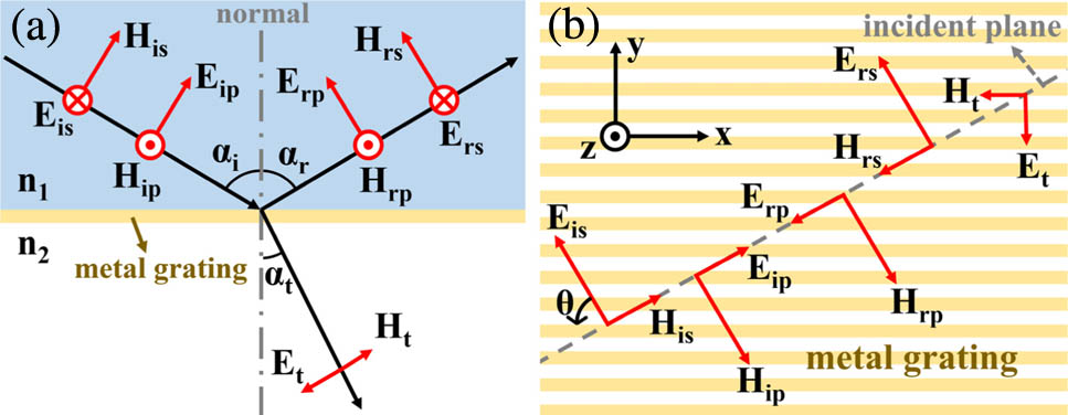
    Fig. 1. Schematic diagram of the electric (E) fields and magnetic (H) fields above and below the metal wire grating, viewing from (a) the incident plane and (b) the top of the metal grating.
    Diagram of the experimental setup.
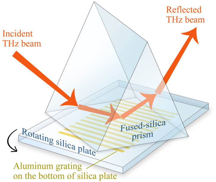
    Fig. 2. Diagram of the experimental setup.
    Experimental and theoretical complex reflection coefficients. (a) The magnitude and (b) the phase of rp and rs when the incident signal is p polarized. (c) The magnitude and (d) the phase of rp and rs when the incident signal is s polarized.
    Fig. 3. Experimental and theoretical complex reflection coefficients. (a) The magnitude and (b) the phase of rp and rs when the incident signal is p polarized. (c) The magnitude and (d) the phase of rp and rs when the incident signal is s polarized.
    (a) Amplitude ratio (|Erp/Ers|) and (b) phase difference (|φp−φs|) between reflected p and s components, when the incident signal is 45° to the s direction and at a 52° incident angle.
    Fig. 4. (a) Amplitude ratio (|Erp/Ers|) and (b) phase difference (|φpφs|) between reflected p and s components, when the incident signal is 45° to the s direction and at a 52° incident angle.
    Polarization states of the (a) incident signal and the reflected signals at (b) θ=34°, (c) θ=58.5°, and (d) θ=90°.
    Fig. 5. Polarization states of the (a) incident signal and the reflected signals at (b) θ=34°, (c) θ=58.5°, and (d) θ=90°.
    Amplitude ratio (|Erp/Ers|, black line) phase difference (|φp−φs|, blue line) between the reflected p and s components, when using Si as a prism and setting the incident angle as 47.5° and the incident light to be 45° linear polarized.
    Fig. 6. Amplitude ratio (|Erp/Ers|, black line) phase difference (|φpφs|, blue line) between the reflected p and s components, when using Si as a prism and setting the incident angle as 47.5° and the incident light to be 45° linear polarized.
    Xudong Liu, Xuequan Chen, Edward P. J. Parrott, Emma Pickwell-MacPherson. Exploiting a metal wire grating in total internal reflection geometry to achieve achromatic polarization conversion[J]. Photonics Research, 2017, 5(4): 299
    Download Citation