Xudong Liu, Xuequan Chen, Edward P. J. Parrott, Emma Pickwell-MacPherson, "Exploiting a metal wire grating in total internal reflection geometry to achieve achromatic polarization conversion," Photonics Res. 5, 299 (2017)
Copy Citation Text
We demonstrate how a metal wire grating can work as a 45° polarization converter, a quarter-wave retarder, and a half-wave retarder over a broadband terahertz range when set up in total internal reflection geometry. Classical electromagnetic theory is applied to understand the mechanism, and equations to calculate the polarization state of reflected light are derived. We use a metal grating with a period of 20 μm and width of 10 μm on a fused silica surface: linearly polarized terahertz light incident from fused silica with a supercritical incident angle of 52° is totally reflected by the metal grating and air. The polarization of the terahertz light is rotated by 45°, 90°, and circularly polarized by simply rotating the wire grating. The performance is achromatic over the measured range of 0.1–0.7 THz and comparable to commercial visible light wave retarders.
Terahertz (THz) frequencies have many advantages in high-speed wireless communications [1,2], material characterization [3,4], and biomedical imaging [5,6]. In these applications, the components controlling the THz polarization, such as polarization rotators and wave plates, are essential. Many designs use birefringent materials, whether artificial or natural, to work as a quarter-wave plate [7–9], but they depend on the wavelength of the light. Some achromatic THz quarter-wave plate designs reported employ stacked birefringent slides [10,11], dielectric grating [12], metamaterials [13,14], or prism reflections [15,16]. These structures have some significant drawbacks, be it the thickness of the stacked crystal slides, the narrow operational bandwidth of the dielectric grating and metamaterial designs, and the requirement of high refractive index materials or multiple reflections for large phase differences for the prism techniques. Woo et al. reported a high conversion ratio slot structure polarization converter, but it performed only at a single frequency [17]. Grady et al. demonstrated a broadband liner polarization converter based on metamaterials [18]. It was highly efficient to convert the incident THz light into a cross-polarization state, but it cannot perform more than one state conversion. The designs referred to above work very well as either a uni-functional quarter-wave plate or a liner polarization converter, but they cannot function as both. A single device that can provide both circular polarization conversion and tunable linear polarization conversion with a broad operation band is therefore desired. Here, we demonstrate an approach that is able to realize an achromatic quarter-wave retarder, half-wave retarder, and 45° linear polarization rotator using a single device, namely, one metal wire grating in total internal reflection (TIR) geometry. The transitions among these three different states can be achieved by simply rotating the wire grating. Metal grating structures working as THz polarizers in both transmission and reflection geometries have been widely reported [19–21]. However, the possible applications of metal gratings in a TIR geometry have not been studied. Based on our previous research, many existing designs that are well characterized in transmission geometry behave quite differently in the TIR geometry [22,23]. Therefore, combining the grating structure and the TIR modality could provide new ways to manipulate the light polarization state without losing the broadband features of the metal grating design.
Sign up for Photonics Research TOC. Get the latest issue of Photonics Research delivered right to you!Sign up now
2. THEORETICAL DERIVATION
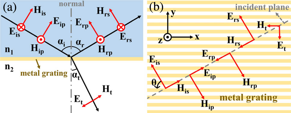
To study the performance of the metal grating in a TIR geometry, we start by theoretically analyzing the reflection and transmission of a grating interface in the oblique incident case. A schematic diagram of the electric and magnetic fields above and below the grating is shown in Figs. 1(a) and 1(b). Above the top surface of the metal grating, the material is isotropic with refractive index of . Between and below the metal grating there is another isotropic material with refractive index of . The thickness of metal in this study is assumed to be above the skin depth for the frequencies of interest, and the period of the metal grating is much smaller than the wavelength to realize broadband performance. The first subscript (, , or ) signifies the incident, reflected, or transmitted electric () and magnetic () fields, respectively, whereas the second subscript ( or ) represents the or component of these fields. , , and are the incident, reflection, and transmission angles, respectively, and is the angle between and the wires in a counterclockwise direction.
Figure 1.Schematic diagram of the electric () fields and magnetic () fields above and below the metal wire grating, viewing from (a) the incident plane and (b) the top of the metal grating.
In this paper, we use the boundary conditions in the and directions to derive the equations of reflection coefficients. In the direction [as shown in Fig. 1(b)], which is parallel to the wires, the tangential component of the field is fully reflected due to the free electrons in the metal wires. By applying Faraday’s law to a small rectangular loop located across the boundary of medium 1 and medium 2 in the plane, the tangential field along the direction can then be expressed in a scalar form of where is the field along direction in medium 1. The tangential component of the field in the direction can be derived by applying Ampere’s law also to a small closed loop across medium 1 and medium 2 in the plane. The free current perpendicular to the metal wire direction does not exist. The boundary condition on the tangential component of the field in the plane can be expressed in scalar form as where and are the magnetic fields along the direction in medium 1 and medium 2, respectively.
The field in the direction is perpendicular to the wire grating and can pass through the grating with low loss. Following the same derivation process of Eq. (1), the tangential field along the direction in the plane can be written as where and represent the field along the direction in medium 1 and medium 2, respectively.
To calculate the polarization state of reflected light, we consider the pure -polarized and -polarized incident cases separately [Fig. 1(b)], as we can decompose an incident light of any polarization state into and components. By combining Eqs. (1)–(3), the field relationship, and Snell’s Law, the reflection coefficients can be derived (see Appendix A–C for further details).
For the -polarized incident case, the reflection coefficients of the and components in the reflected light can be written as For the -polarized incident case, the reflection coefficients of the and components in the reflected light can also be achieved as
3. EXPERIMENTAL RESULTS
From the theoretical analysis, Eqs. (4)–(7) are still satisfied when the incident angle is supercritical (in cases where ). Furthermore, the use of non-dispersive media should result in these derived equations being independent of frequency, thereby realizing achromatic performance within the design parameters of the grating itself. To experimentally verify the derived equations, we put an equilateral triangle fused-silica prism (with a bottom surface of ) in a 45° incident THz reflection system. A fused-silica plate with aluminum metal grating on the opposite surface is attached to the prism, with an index matched liquid used to minimize any reflections between the prism and plate. The wire width and period of the grating are 10 and 20 μm, respectively, and the metal thickness is 200 nm. The fused-silica prism and plate both have a refractive index of 2 [24]. Fused silica has a high absorption coefficient at high THz frequencies, but for frequencies below 1 THz, the absorption coefficient is less than [24]. A schematic of the setup is shown in Fig. 2.
The incident THz light refracted into the silica makes an angle of 52.6° with the grating surface. The incident THz light is set as pure - or -polarized separately. Under each circumstance, we record the reflected and signals at different values by rotating the silica plate. A reference signal is recorded by replacing the grating plate by another silica plate with a gold layer on the surface, and is regarded as the incident signal. The complex reflection coefficients are then calculated by comparing the reflected signal to the reference signal in the frequency domain. The results are shown in Fig. 3 for both and polarizations.
Figure 3.Experimental and theoretical complex reflection coefficients. (a) The magnitude and (b) the phase of and when the incident signal is polarized. (c) The magnitude and (d) the phase of and when the incident signal is polarized.
As the reflection coefficients are a function of frequency, we calculate the result by taking the average over 0.1–0.7 THz (the useable bandwidth of our THz system). The error bars plotted in Fig. 3 show the variation range from 0.1 to 0.7 THz. Figure 3 shows that the experimental results agree well with the theoretical predictions for both the magnitude and the phase. The error bars are very small, suggesting that the coefficients are indeed essentially frequency independent. The device therefore exhibits broadband achromatic characteristics.
With this experimental verification of our theory, we can use the theory to predict the output by giving a certain incident polarization state and values of and . An ideal design would be if we can realize the device as a quarter-wave retarder, half-wave retarder, and a polarization rotator by just changing the value, as can be easily varied by rotating the grating plate. By theoretical calculation we find that, when and the incident state is 45° linearly polarized to the direction, we are able to achieve quarter-wave retardance, half-wave retardance, and 45° linear rotation functions at the values of 90°, 58.5°, and 34°, respectively.
We use the setup shown in Fig. 2 to experimentally verify the expected output. The incident angle of the THz system is changed to 44° to induce a desired 52° incident angle at the grating surface. A polarizer is used between the emitter and the prism to filter the incident light to be 45° linear polarized. By recording the reflected signals at values of 90°, 58.5°, and 34°, we calculate the magnitude ratio and phase difference between the reflected and components and show the results in Fig. 4. It shows a very good match between experimental results and theoretical prediction for data from 0.1 to 0.7 THz. The small spread of phase angles apparent for different frequencies can be used to determine whether the device can be designated as achromatic. The amplitude fluctuation ranges of this design for the quarter- and half-wave retarders are , and , , respectively. Comparing the spread of phase angles in this work for the quarter- (16°) and half- (10°) wave retarder performance with the performance of commercially available achromatic wave plates for visible light frequencies (11° for quarter-wave plate and 21° for half-wave plate, Ref. [25]) shows that these are of comparable quality. The commercial tunable THz polarization converter [26] can work as a quarter-wave plate or a half-wave plate only for a single frequency. Its insertion loss from three separate quartz plates will be much higher than that in this work; the adjustment of three quartz plates to switch between the quarter- and half-wave plate for different frequencies is complex. The phase angle spread of the quarter-wave retarder case in this work is slightly higher than those recorded in Refs. [10,13] (6° and 9°, respectively), however. The most likely source of the increased phase chromaticity in our results is the time-domain pulse shift experimental error, and not due to the wave plate design itself. The phase is extremely sensitive to the pulse position as a 25 fs pulse shift will result in a 9° error at 1 THz. A 25 fs pulse shift can be easily induced by a 2.3 μm shift of the reflection plane when rotating the grating plate between measurements.
Figure 4.(a) Amplitude ratio () and (b) phase difference () between reflected and components, when the incident signal is 45° to the direction and at a 52° incident angle.
To observe the polarization state changing from input to output more intuitively, we plot Fig. 5 to compare these polarization states. In Fig. 5, the incident state is recovered by using the reflection from a silica–metal plate. The components of the different frequencies are normalized to 1. The result shows that the reflected signal is completely converted to the desired state. The conversion of different output states is achieved by simply rotating the grating plate. The full frequency range studied follows the same conversion. The absorption of at high frequencies limits the working bandwidth in this work. The reason to choose prism is that its refractive index () can lead to the three different polarization conversions under the same incident angle. By using a low-absorption Si prism, one can still achieve two polarization conversions of half- and quarter-wave retardance under the same incident angle of 47.5°, when the incident light is 45° polarized and is set to 56° and 90°, respectively (see Appendix D for further details). In this case, the working bandwidth of the device is limited only by the grating dimension, which can be designed up to 5 THz by simple micro-fabrication techniques. The total loss of the device is very small, and is caused by both the insertion losses of the air–silica–air interfaces and the absorption when propagating through the device. By properly designing the prism faces, one can also apply this device to be used in transmission geometry. The device can ideally work as a high-efficiency, ultra-broadband quarter-wave retarder, and 45° linear polarization rotator.
Figure 5.Polarization states of the (a) incident signal and the reflected signals at (b) , (c) , and (d) .
In conclusion, we have developed a THz polarization converter based on a metal wire grating operating in TIR geometry. This is a fundamentally new way to achieve achromatic polarization rotation: we have developed the theory and verified it with measurements of a real THz device. Our design provides an approach to achieve an achromatic 45° polarization rotation and quarter-wave and half-wave retardance using only a single device. With appropriate choice of grating parameters and materials, the design could be extended for use at other frequencies, making this work relevant to the broader optics community.
APPENDIX A: VERIFICATION OF SNELL’S Law
According to the Maxwell–Faraday equation, the boundary condition of the field can be expressed in a propagation-wave form as where is the angular frequency; is any unit vector on the reflection plane; , and are the incident, reflected, and transmitted electric fields, respectively; and , and are the wave vectors of the incident, reflected, and transmitted waves, respectively. To satisfy this boundary condition for any direction of and any time , we should have Expressing Eq. (A2) in scalar form by using the geometric relationship, we get where and are the refractive indices of medium 1 and medium 2, respectively; and , and are the incident, reflected, and transmitted angles, respectively. Equation (A3) verifies that Snell’s law still holds when light is obliquely incident to a grating surface.
APPENDIX B: GEOMETRY RELATIONSHIPS OF Et, Ht, AND
As shown in Fig. 1, in the established coordinate, we can express the direction of as and must be perpendicular to : From the boundary analysis in the and directions in the paper, we know that has no component and has no component. By expressing and in these coordinates, we have Combining Eqs. (B1)–(B5), we get Equations (B6) and (B7) give the geometry relationships of , , and their components on the reflection plane.
APPENDIX C: SOLUTION OF THE BOUNDARY CONDITIONS
Utilizing Eqs. (B6) and (B7), when the incident light is pure polarized, the boundary conditions of Eqs. (1)–(3) in this paper can be expressed by the incident, reflected, and transmitted fields as The field relationship in a isotropic material is
In combining Eqs. (A3), (C1), and (C2), we are able to calculate the incident reflection coefficients as
Similar to the -incident case, the boundary conditions when the incident light is pure polarized can be expressed as By combining Eqs. (A3), (C2), and (C5), the reflection coefficients can be calculated as
APPENDIX D: POLARIZATION CONVERSION WHEN USING SI
Fused silica has a refractive index of 2, which makes it possible to perform as a 45° rotator and a half-wave and quarter-wave retarder under one incident angle. When the 45° rotation is not necessary, a Si prism can be used to greatly improve the working bandwidth of the device by providing a much smaller dispersion and absorption. The theoretical output of the device when using a Si prism and Si plate (assuming ) when the incident angle is 47.5° and the incident light is 45° linear polarized is shown in Fig. 6. The half- and quarter-wave output is achieved when is set to 56° and 90°.
Figure 6.Amplitude ratio (, black line) phase difference (, blue line) between the reflected and components, when using Si as a prism and setting the incident angle as 47.5° and the incident light to be 45° linear polarized.
[5] S. Fan, B. S. Y. Ung, E. P. J. Parrott, V. P. Wallace, E. Pickwell-MacPherson. In vivo terahertz reflection imaging of human scars during and after the healing process. J. Biophoton..
Xudong Liu, Xuequan Chen, Edward P. J. Parrott, Emma Pickwell-MacPherson, "Exploiting a metal wire grating in total internal reflection geometry to achieve achromatic polarization conversion," Photonics Res. 5, 299 (2017)