
Qibin Feng, Qiyu Sun, Kejing Li, Zi Wang, Lü Guoqiang. Surface Microstructure-Based Ultra-Thin Backlight Unit Lens Design[J]. Acta Optica Sinica, 2023, 43(7): 0722002
- Acta Optica Sinica
- Vol. 43, Issue 7, 0722002 (2023)
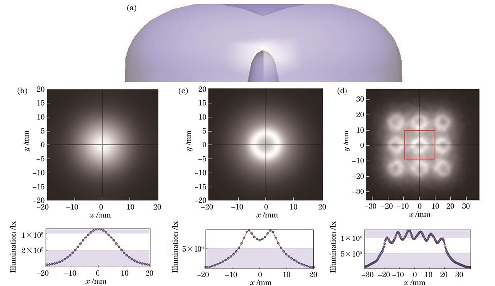
Fig. 1. Double free-form surface lens model and illuminance distributions simulated under different light sources. (a) Double free-form surface lens model; simulated illuminance distributions for (b) point light source, (c) extended light source, and (d) extended light source array

Fig. 2. Schematic diagram of lens design
Fig. 3. Simulated illumination distributions of traditional TIR lens. (a) Point light source; (b) extended light source
Fig. 4. Design schematic diagram of surface S1
Fig. 5. Microstructure design diagram
Fig. 6. Illuminance curve of surface S1 for extended light source
Fig. 7. Schematic diagram of optimization design of surface S1-1
Fig. 8. Illuminance curves of surface S1 and optimized surface S1-1 for extended light source
Fig. 9. Illuminance curves of surface S1-1 and quadratic optimized surface S1-2 for extended light source
Fig. 10. Extended light ray graphs. (a) Surface S1-1; (b) quadratic optimized surface S1-2
Fig. 11. Simulated illuminance diagrams of lens. (a) Extended light source; (b) extended light source array
Fig. 12. Illuminance curves based on extended light sources with traditional double free-form surface lens and lens designed in this paper

Set citation alerts for the article
Please enter your email address
© Copyright 2018-2021 | Chinese Laser Press. All Rights Reserved 沪ICP备15018463号-20