• Laser & Optoelectronics Progress
  • Vol. 59, Issue 17, 1722006 (2022)
Shuo Qin1、2、*
Author Affiliations
  • 1Department of Avionics, Air Force Aviation Maintenance Technical College, Changsha 410200, Hunan , China
  • 2Aviation Electronic Maintenance Laboratory, Aircraft Maintenance Engineering Technology Research Center of Hunan Province, Changsha 410200, Hunan , China
  • show less
    DOI: 10.3788/LOP202259.1722006 Cite this Article Set citation alerts
    Shuo Qin. Model Predictive Thermal Control Method for Precision Lens System[J]. Laser & Optoelectronics Progress, 2022, 59(17): 1722006 Copy Citation Text show less
    Basic structure of the model predictive controller
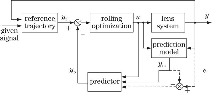
    Fig. 1. Basic structure of the model predictive controller
    Pseudo random input and output signal of precision lens system
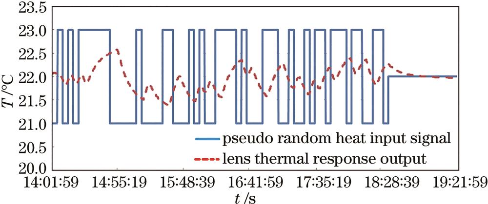
    Fig. 2. Pseudo random input and output signal of precision lens system
    Autocorrelation analysis curve of pseudo random thermal disturbance input signal
    Fig. 3. Autocorrelation analysis curve of pseudo random thermal disturbance input signal
    Structure of the thermal control experimental platform
    Fig. 4. Structure of the thermal control experimental platform
    Physical map of the high precision temperature control experimental platform
    Fig. 5. Physical map of the high precision temperature control experimental platform
    Structure diagram of lens system and cooling water jacket. (a) Structure of precision lens system; (b) appearance drawing of the cooling water jacket
    Fig. 6. Structure diagram of lens system and cooling water jacket. (a) Structure of precision lens system; (b) appearance drawing of the cooling water jacket
    Schematic diagram of the temperature sensor. (a) Installation position of the sensor; (b) installation method of the sensor
    Fig. 7. Schematic diagram of the temperature sensor. (a) Installation position of the sensor; (b) installation method of the sensor
    Experimental scene diagram
    Fig. 8. Experimental scene diagram
    Temperature curve of the temperature control point of the lens system. (a) Experiment 1; (b) experiment 2
    Fig. 9. Temperature curve of the temperature control point of the lens system. (a) Experiment 1; (b) experiment 2
    Variation trend of Z4 in the wave aberration of the lens system. (a) Experiment 1; (b) experiment 2
    Fig. 10. Variation trend of Z4 in the wave aberration of the lens system. (a) Experiment 1; (b) experiment 2
    Shuo Qin. Model Predictive Thermal Control Method for Precision Lens System[J]. Laser & Optoelectronics Progress, 2022, 59(17): 1722006
    Download Citation