
Huifang Liu, Wu Zhou, Xiaoshu Cai, Lei Zhou, Yan'ang Guo. Three-Dimensional Particle Tracking Velocimetry Based on Light Field Imaging[J]. Acta Optica Sinica, 2020, 40(1): 0111014
- Acta Optica Sinica
- Vol. 40, Issue 1, 0111014 (2020)
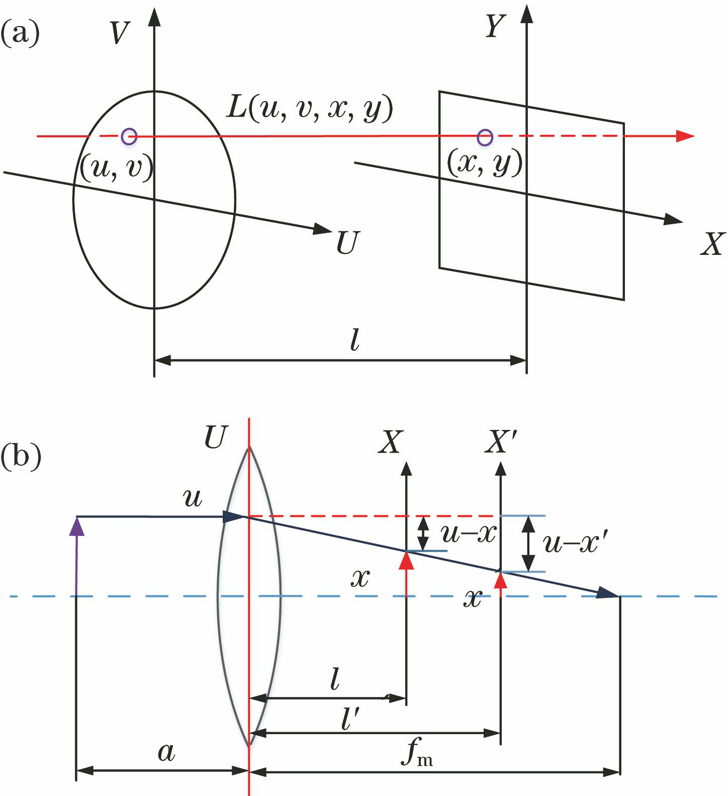
Fig. 1. Light field schematic. (a) Diagram of light field biplane parameterization; (b) refocusing schematic
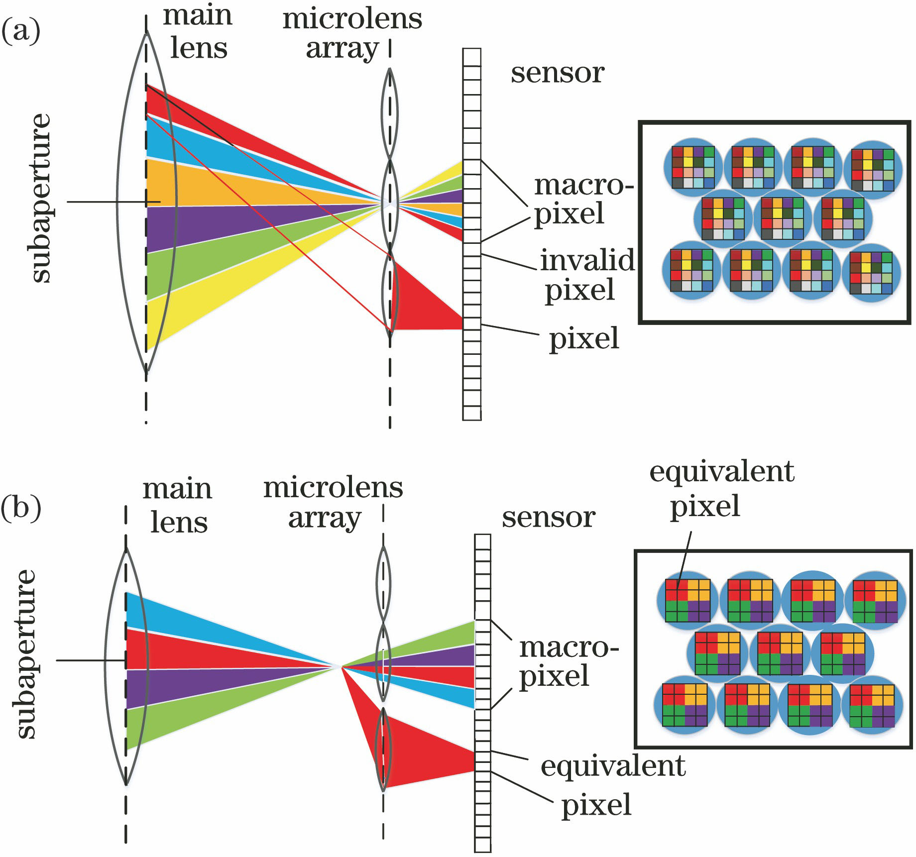
Fig. 2. Schematics of light transmission sampling of two plenoptic cameras. (a) Unfocused plenoptic camera;(b) focused plenoptic camera
Fig. 3. Refocusing images. (a) Focus on far; (b) focus on near
Fig. 4. Simplified diagram of light transmission of focused plenoptic camera
Fig. 5. Raw light field image and all-in-focus image. (a) Partial enlarged raw light field image; (b) all-in-focus image
Fig. 6. Diagram of experiment device for calibration
Fig. 7. Curve of refocusing coefficient-sharpness
Fig. 8. Results of depth calibration. (a) 7 points; (b) 9 points
Fig. 9. Reprojection error. (a) Corners error; (b) average reprojection error
Fig. 10. Flow chart of particle tracking
Fig. 11. Simplified flow chart of light field PTV technology
Fig. 12. Schematic of experimental system. (a) Experimental device; (b) measuring area
Fig. 13. Tracking results of two adjacent frame particles. (a) Velocity slices in z direction; (b) velocity slices in y direction; (c) angular velocity
| |||||||||||||||||||
Table 1. E of different depth calibration methods

Set citation alerts for the article
Please enter your email address
© Copyright 2018-2021 | Chinese Laser Press. All Rights Reserved 沪ICP备15018463号-20