• Acta Optica Sinica
  • Vol. 43, Issue 12, 1222001 (2023)
Jie Chen1, Tuanjie Xia2, Tong Yang1, Lei Yang1、*, and Hongbo Xie1
Author Affiliations
  • 1Key Laboratory of Opto-Electronic Information Technology, Ministry of Education, School of Precision Instruments and Opto-Electronics Engineering, Tianjin University, Tianjin 300072, China
  • 2Advanced Photoelectric Detection Research and Development Center, Shanghai Aerospace Control Technology Institute, Shanghai 201100, China
  • show less
    DOI: 10.3788/AOS221609 Cite this Article Set citation alerts
    Jie Chen, Tuanjie Xia, Tong Yang, Lei Yang, Hongbo Xie. Research on Long-Wave Infrared and Laser Common-Aperture Dual-Mode Guided Optical System[J]. Acta Optica Sinica, 2023, 43(12): 1222001 Copy Citation Text show less
    Schematic diagram of optical structure
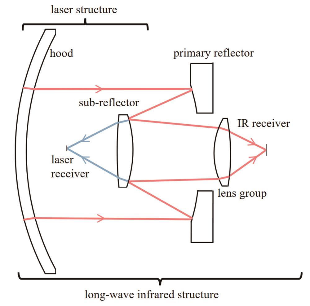
    Fig. 1. Schematic diagram of optical structure
    R-C structure ray trace diagram
    Fig. 2. R-C structure ray trace diagram
    Geometric representation of optical system OTF with annular obscuration. (a) Annular pupil; (b) two staggered annular exit pupils
    Fig. 3. Geometric representation of optical system OTF with annular obscuration. (a) Annular pupil; (b) two staggered annular exit pupils
    Diffraction limit of modulation transfer function at different obscuration ratios
    Fig. 4. Diffraction limit of modulation transfer function at different obscuration ratios
    Long-wave infrared optical initial structure
    Fig. 5. Long-wave infrared optical initial structure
    Structure diagram of long-wave infrared optical module. (a) Two-dimensional structure diagram; (b) three-dimensional structure diagram
    Fig. 6. Structure diagram of long-wave infrared optical module. (a) Two-dimensional structure diagram; (b) three-dimensional structure diagram
    MTF curves for a long-wave infrared optical module
    Fig. 7. MTF curves for a long-wave infrared optical module
    Image quality evaluation of long-wave infrared optical module. (a) Distortion diagram; (b) standard spot diagram
    Fig. 8. Image quality evaluation of long-wave infrared optical module. (a) Distortion diagram; (b) standard spot diagram
    1.064 μm laser receiver module structure diagram
    Fig. 9. 1.064 μm laser receiver module structure diagram
    Image plane analysis of 1.064 μm laser receiver module. (a) Fraction of enclosed energy; (b) footprint diagram
    Fig. 10. Image plane analysis of 1.064 μm laser receiver module. (a) Fraction of enclosed energy; (b) footprint diagram
    MTF curves of long-wave infrared optical modules at different temperatures. (a) -40 ℃; (b) 0 ℃; (c) 20 ℃; (d) 60 ℃
    Fig. 11. MTF curves of long-wave infrared optical modules at different temperatures. (a) -40 ℃; (b) 0 ℃; (c) 20 ℃; (d) 60 ℃
    Standard spot diagram of long-wave infrared optical module at different temperatures. (a) -40 ℃; (b) 0 ℃; (c) 20 ℃; (d) 60 ℃
    Fig. 12. Standard spot diagram of long-wave infrared optical module at different temperatures. (a) -40 ℃; (b) 0 ℃; (c) 20 ℃; (d) 60 ℃
    ParameterLong-wave infrared module1.064 μm laser receiver module
    Wavelength8-12 μm1.064 μm
    DetectorPixel size 12 μmImage diameter 0.5 mm
    FOV4°×3°±0.3°
    Optical total length≤100 mm
    Table 1. Specifications of long-wave infrared optical module and 1.064 μm laser receiving optical module
    Parametere12e22r1 /mm

    r2 /

    mm

    d /mm
    Specification1.21428614.714286-66-39.6-23.1
    Table 2. Initial structural parameters of long-wave infrared optical module
    ClassificationTolerance typeTolerance value
    Surface toleranceThickness /mm±0.02
    Decenter /mm±0.02
    Tilt /(°)±0.033
    Radius /fringe2
    Aspherical surface tolerancePV /μm0.5
    Element toleranceDecenter /mm±0.02
    Tilt /(°)±0.033
    Table 3. Tolerance analysis of long-wave infrared system
    Jie Chen, Tuanjie Xia, Tong Yang, Lei Yang, Hongbo Xie. Research on Long-Wave Infrared and Laser Common-Aperture Dual-Mode Guided Optical System[J]. Acta Optica Sinica, 2023, 43(12): 1222001
    Download Citation