State Key Laboratory of Precision Measurement Technology and Instruments, Department of Precision Instrument, Tsinghua University, Beijing 100084, China
Xu Yuan, Bo Wang, "Using single wavelength light to improve the synchronization accuracy of the White Rabbit system," Chin. Opt. Lett. 15, 101202 (2017)
Copy Citation Text
We demonstrate a new synchronization method for the White Rabbit system. Signals are transmitted in a single mode fiber in both directions with the same light wavelength. Without the complex calibration process of the fiber asymmetry parameter, the new method reduces the effect of chromatic dispersion and improves the synchronization accuracy. The experiment achieves timing synchronization accuracy below 200 ps over 50 km fiber constructed by different companies’ fiber spools. The proposed method would make White Rabbit technology immune to the chromatic dispersion of fiber links and can be applied to long distance synchronization.
High precision time synchronization technology has been widely required in phased array antenna and related astronomical observations[1,2], navigation[3,4] telecommunication[5], and timing control systems[6]. Satellite-based global positioning and navigation systems (GNSS), such as the Global Positioning System (GPS)[7], Beidou[8], and the GLObalnaya NAvigatsionnaya Sputnikovaya Sistema (GLONASS)[9], can provide nanosecond (ns) level synchronization precision. However, in some applications, satellite signals are unavailable. For example, the radio astronomical telescope Square Kilometer Array (SKA)[10,11] requires precise time synchronization under the radio silent condition. Furthermore, for the underground accelerator and indoor localization system, they also cannot receive the satellite signals. Fiber-based White Rabbit (WR)[12] time synchronization technology is an excellent alternative synchronization solution. It can provide sub-ns time synchronization within 10 km. Since its high precision and compliance with Ethernet standards, WR now has a wide range of applications in cosmic particle detectors and timing control systems[13–17]. But in practical applications, the one-way transmission delay is hard to estimate precisely because different wavelengths of light are used in the uplink (slave to master) and downlink (master to slave). Furthermore, the long distance urban fiber link is connected section by section. Different fiber sections may be supplied by different companies. All of these factors limit the synchronization distance, which means the synchronization accuracy will be decreased at longer distances.
In this Letter, we demonstrate a synchronization method for the WR system to eliminate the effect of chromatic dispersion. Different to the conventional WR method, two laser lights with the same wavelength are used to transmit and receive signals in a single fiber. A pair of optical transceiver modules is used to modulate the electric signals on the laser light. The proposed method brings significant improvement on the long distance synchronization accuracy. On a 50 km fiber link, which is constructed by different companies’ fiber spools, the synchronization error maintains below 200 ps. As a comparison, the timing synchronization accuracy using the conventional WR method is around 1.5 ns. It makes the proposed synchronization method available for the already deployed fiber link without complicated calibration.
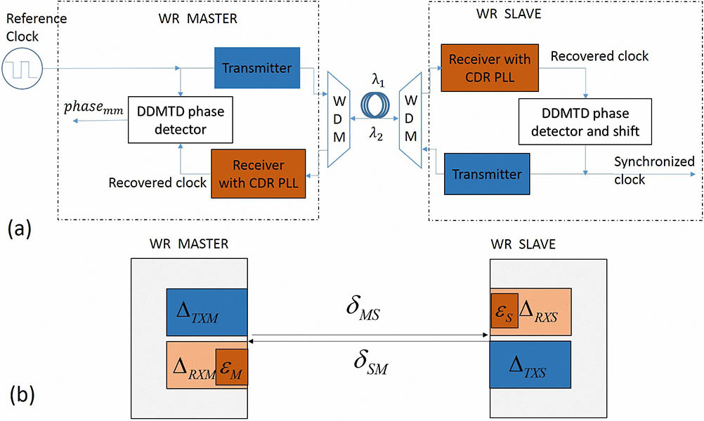
WR is a solution to provide sub-ns synchronization accuracy and reliable data transfer for multi-users over an Ethernet-based topology network. Initially, the WR system is used as a timing system for the experimental physics facilities[18]. A typical WR link consists of the WR master and the WR slave[19], as is illustrated in Fig. 1(a). Based on the Synchronous Ethernet technique[20], the slave’s internal clock reference is locked to the master clock via the phase lock loop (PLL). To get the precise time delay between the master and slave, the precise time protocol (PTP) is performed to calculate the coarse link delay through exchanging the timestamp message[21,22]. Because the recovered clock is asynchronous to the local reference clock, a Digital Dual Mixer Time Difference (DDMTD) phase detector is used to enhance the resolution of timestamps and achieve sub-ns synchronization accuracy[23]. As WR is compatible to the gigabit Ethernet standards 1000BASE-BX10, a single mode fiber and different wavelength light transmitting in both directions are required. For example, using the small form-factor pluggable transceivers (SFPs), the master transmits and receives laser light of 1490 and 1310 nm, respectively. The salver transmits and receives laser light of 1310 and 1490 nm, respectively[24]. A WR link established between two terminals is characterized by the hardware delays and fiber propagation latencies presented in Fig. 1(b).
Sign up for Chinese Optics Letters TOC. Get the latest issue of Chinese Optics Letters delivered right to you!Sign up now
Figure 1.Link model of WR system. (a) Schematic diagram of WR system, (b) delay model of WR system. , are the transmission and reception delays of the master device. , are the transmission and reception delays of the slave device. , are the bitslide values while aligning the received data stream. , are the one-way propagation latencies in fiber. WDM, wavelength division multiplexer; CDR, clock data recovery circuits.
The transmission and reception delays , , , and are the hardware delays of master and slave; they are unknown and can be recognized as constant in the case of the sub-ns level synchronization. The bitslide values (, ) can be obtained from WR software[25]. The value of one-way fiber propagation latencies require it to be estimated. Based on the WR model, the round trip is described as
In the synchronization process, the slave device requires estimating the one-way master to slave delay:
For the conventional WR method, as the result of chromatic dispersion, the fiber propagation latencies . Therefore, the WR software defines a parameter to compensate the propagation asymmetry. If the link consists of one type of fiber, the value of will be independent of the fiber length, and the WR synchronization error between the master and slave nodes depends on the accuracy of parameter .
To obtain the value of hardware delays (, , , ) and the asymmetry parameter (), CERN (European Organization for Nuclear Research) provides the calibration procedure[25]. In the procedure, it is necessary to calibrate the coefficient of the fiber in the WR link in advance, and the procedure cannot be applied to the fiber link that consists of different fiber types (for single mode G652 fiber, the coefficient is different for the fiber produced by a different company). While for the deployed urban fiber link, it is spliced section by section. Different fiber sections may be provided by different producers. Therefore, is hard to be measured precisely for the deployed urban fiber link. From the research results of Ref. [26], if has a variation of , the value of will change to 150 ps for the 10 km fiber link. Thus, the performance of WR synchronization accuracy is worsened in the practical application.
To eliminate the effect of chromatic dispersion, we demonstrate a single wavelength WR synchronization method. The schematic diagram of the proposed WR synchronization scheme is shown in Fig. 2(a). In the experiment, a pair of unidirectional SFPs transmits and receives Ethernet signals in a separated fiber link with the same 1550 nm wavelength. A couple of optical fiber circulators are used to route the uplink light and downlink light into a single fiber.
Figure 2.(a) Schematic diagram of the proposed WR synchronization method. (b) The delay model of the proposed WR link. , , , and are the transmission delays in fiber circulators.
Based on the link model, the round trip is described as
Once the master and slave are synchronized, and are fixed. , , , and are the transmission delays in fiber circulators. As the fiber length of the circulators is around 1 m, the transmission delays can also be recognized as constant in the case of sub-ns level synchronization. The sum of hardware delays and transmission delays in fiber circulators can be considered as new hardware delays and be described as
Since the wavelength of light in the up and down link is the same, the fiber latencies in the uplink and downlink are equal;
Therefore, the precise value of the one-way master to slave delay is
As the precise value of and can be measured, the link delay asymmetry just comes from the hardware delays (, ). The hardware delays of each WR device can be calibrated with a WR calibrator whose and are known. After the WR device under calibration is configured as the slave and synchronized with the WR calibrator, the correction value to compensate the slave hardware and circulator asymmetry can be measured with the time interval counter (TIC) by comparing the pulse per second (1PPS) signal’s time deviation, represented as . Thus, and can be calculated[25]:
Once the hardware delay of the WR device is calibrated precisely, the accurate one-way link delay can be transmitted to the slave.
To verify the performance of calibration and synchronization, the new hardware delay values are written into the configuration of the WR device, and the 1PPS signals generated by the master and slave are connected to a TIC. Figure 3 describes the synchronization result of the two WR devices connected in a short distance (two fiber circulators are connected directly). Using the proposed method, the synchronization error of two WR devices is shown in Fig. 3(a), which has a mean error value of 8.7 ps and a standard deviation of 27 ps. As a comparison, Fig. 3(b) describes the result of the conventional WR scheme, where a 3-m-long fiber and two bidirectional SFPs (operating at 1310/1490 nm) are connected, in which a mean synchronization error value of 5.7 ps and standard deviation of 31 ps is obtained. The measurement results of two WR synchronization schemes are similar, and their mean synchronization values are less than 10 ps. It means that the hardware delays of the two WR devices have been calibrated correctly in these two schemes.
Figure 3.(Color online) Result of two synchronization schemes. (a) Time deviation of the proposed method when the WR master and slave are connect directly. (b) Time deviation of the conventional method when the WR master and slave are connect by a 3-m-long fiber.
To further demonstrate the accuracy of the proposed synchronization method, a 5 km and a 50 km standard G652 fiber are connected into the link in turn. Figure 4 shows the synchronization results of different synchronization schemes when a 5 km fiber [YOFC, the dispersion parameter is for 1550 nm and for 1285–1340 nm] is connected. For the conventional WR scheme, we first calibrate the asymmetry parameter of the 5 km fiber and write the value of into the configuration of the WR device. The black line is the synchronization result, in which a mean synchronization error value of 174 ps and a standard deviation of 32 ps is obtained. For the proposed scheme, there is no requirement on the asymmetry parameter calibration. The red line is the result of the proposed scheme, which has a mean synchronization error value of 59 ps and a standard deviation of 31 ps. The result indicates that the proposed scheme has a better performance as the asymmetry effect of propagation is reduced.
Figure 4.(Color online) Result of two schemes when the WR master and slave are connected by a 5 km fiber.
As the practical fiber network may consist of fiber provided by different manufacturers or different batches from same manufacturer, the asymmetry parameter of each fiber section may be different. The difference brings significant impact on the practical application of the conventional scheme, and the value of fiber asymmetry is hard calibrate precisely. To simulate the practical application case and verify the performance of proposed scheme, we choose a 50 km fiber spool provided by a different manufacturer (CORNING), while the parameters (from the data sheet) of the 5 and 50 km fiber spools are the same. The result is described in Fig. 5.
Figure 5.(Color online) Result of two schemes when the WR master and slave are connected by a 50 km fiber.
In the conventional scheme, we keep the value of unchanged and connect the 50 km fiber into the link. The black line is the synchronization performance of the 50 km fiber link in the conventional WR scheme, which has a mean synchronization error value of 1572 ps and a standard deviation of 39 ps. The result shows that the fiber provided by different manufacturers actually has a big difference in asymmetry parameter values, and this difference makes a serious impact on long distance synchronization in the conventional WR scheme. For the proposed scheme, a 50 km fiber is directly connected into the link without recalibration. The red line is the result of the 50 km fiber link in the proposed scheme, which has a mean synchronization error value of 130 ps and a standard deviation of 27 ps. The result indicates that the proposed scheme can maintain high synchronization precision, and it is available for the fiber link provided by different manufacturers.
For the proposed scheme, the origination of the synchronization error includes the wavelength offset and wavelength drift of SFPs and hardware delay fluctuations. To decrease the impact of wavelength error, we choose the SFP pair whose wavelength difference is about 0.1 nm. The wavelength drift of the SFPs is no more than 0.05 nm. The hardware delays and fiber circulator delays will fluctuate within tens of picosecond with the change of temperature[27], but the synchronization result can be accepted at the synchronization accuracy of the sub-ns level.
Sign up for Chinese Optics Letters TOC. Get the latest issue of Chinese Optics Letters delivered right to you!Sign up now
In conclusion, we demonstrate a synchronization scheme for the WR system. The fiber circulators and unidirectional SFPs allow the signals to be transmitted in the same wavelength light via a single fiber. The proposed synchronization method brings significant improvements. The calibration procedures have been simplified. The sum of the hardware and fiber circulator delays can be measured in a single step, and coefficient does not need to be calibrated. Secondly, the performance of the synchronization has been obviously improved. In the conventional WR scheme, the accuracy of limits the precise measurement of the one-way link delay, and the coefficient is different for the fiber links from different manufacturers and environment temperature. In our scheme, different types of fibers can be connected directly, and the performance of synchronization will not be influenced. In addition, the new synchronization method is available for the already deployed fiber link without complicated calibration, and the performance maintains within 200 ps in the distance of 50 km.
[4] S. Younis. Time acquisition in a wireless position determination system(2005).
[5] L. Hanzo, L. L. Yang, E. L. Kuan, K. Yen. Single-and multi-carrier DS-CDMA: multi-user detection, space-time spreading, synchronization, standards and networking(2003).
[12] J. Serrano, M. Cattin, E. Gousio, E. van der Bij, T. Włostowski, G. Daniluk, M. Lipiński. Proceedings of IBIC2013, THBL2(2013).
[13] D. Beck, R. Bar, M. Kreider, C. Prados, S. Rauch, W. Terpstra, M. Zweig. Proceedings of PCaPAC2012, FRIA01(2012).
[14] G. Gong, S. Chen, Q. Du, J. Li, Y. Liu, H. He, WEBHMULT04(2011).
[15] M. Lipinski, T. Wlostowski, J. Serrano, P. Alvarez, J. D. G. Cobas, A. Rubini, P. Moreira. IEEE International Symposium on Precision Clock Synchronization for Measurement, Control and Communication Proceedings, 1(2012).
[19] P. Moreira, J. Serrano, T. Wlostowski, P. Loschmidt, G. Gaderer. International Symposium on Precision Clock Synchronization for Measurement, Control and Communication, 1(2009).
[20] T. Wlostowski. Precise time and frequency transfer in a white rabbit network(2011).
[21] J. Eidson, L. Kang. 2nd ISA/IEEE Sensors for Industry Conference, 2002(2002).
[22] M. Lipiński, T. Włostowski, J. Serrano, P. Alvarez. IEEE International Symposium on Precision Clock Synchronization for Measurement, Control and Communication, 25(2011).
[23] P. Moriera, P. Alvarez, J. Serrano, I. Darwezeh, T. Wlostowski. IEEE International Frequency Control Symposium, 449(2010).
[24] (2017).
[25] . White Rabbit calibration procedure(2015).
[26] W. Pan. Research on the High Precision Time Measurement System for the LHAASO Project(2014).
Xu Yuan, Bo Wang, "Using single wavelength light to improve the synchronization accuracy of the White Rabbit system," Chin. Opt. Lett. 15, 101202 (2017)