Abstract
Multicolor holography can faithfully record the color, depth, parallax, and other properties of scenes and have thus found numerous applications, for example, in optical document security, nonvolatile data storage, and virtual or augmented reality systems. Nanophotonic metasurfaces present multiple degrees of freedom to manipulate the properties of optical fields at visible wavelengths. These in turn provide opportunities for metasurface-based multicolor holography. We describe recent developments in multicolor metasurface holograms. These are categorized based on their color-separating mechanisms rather than their structural properties, such as whether they are plasmonic or dielectric. We hope this review will provide readers with new insights and thus help extend applications of metasurface-based multicolor holography to other fields.1 Introduction
Holography is a wavefront reconstruction technology that was pioneered by Dennis Gabor in the 1940s.1 In addition to recording amplitude and phase information, it is often required that a hologram also records the color of an object so that the reconstruction is as vivid as possible. In principle, color information can be reconstructed by a hologram consisting of three independent interference patterns, i.e., those recorded by red (R), green (G), and blue (B) laser beams.2 However, crosstalk images will be produced as well, which are generated, for example, when the red interference pattern also diffracts green and blue light. Traditional solutions to this problem include volume reflection holograms,3 rainbow holograms,4 and white light-processing holograms.5 Volume reflection holograms use an emulsion layer as the recording medium in which three sets of highly wavelength-selective fringe patterns are formed. Rainbow holograms reconstruct the image of a colorful object and a slit simultaneously. When viewing the reconstructed image from the original position of the slit, three superimposed images of the object are seen (corresponding to RGB color channels). White light-processing holography uses narrowband spatial filters at appropriate locations in the Fourier plane. The filtered light then recombines to form a color image at the output plane. Multicolor holography based on surface plasmons has also been reported.6 In this technique, color information is encoded via the use of nanostructures supporting surface plasmon resonances to control the scattering of each color channel.
Recent years have seen much interest for the use of metasurfaces for various applications in optics due to the flexibility with which they can be used to manipulate the wavefront of light.7–16 Metasurface-based wavefront control generally falls into the following categories based on their working principles:17–19 plasmonic resonance, propagation phase, Mie resonance, and geometric phase. Plasmonic resonance-type metasurfaces usually contain subwavelength structures that support localized surface plasmon modes,20 gap surface plasmon modes,21 and so on.22 The phase delay of the scattered light can be controlled by modifying the geometric parameters of these structures.23–25 Propagation phase-type metasurfaces usually consist of nanopillars made from low refractive index materials such as or .26,27 Each nanopillar can be regarded as a vertical waveguide. The propagation phase accumulated by passing through the waveguide is determined by its diameter.14,28,29 Mie resonance-type metasurfaces generally have building blocks of high refractive index that support magnetic/electric dipole or higher modes.30–33 One example is Huygens’ metasurface,34–36 where the electric and magnetic dipoles superpose to form near-zero reflection, while at the same time providing phase coverage to the transmitted light. Geometric phase-type metasurfaces have anisotropic nanostructures of the same geometry but varying orientations. When circularly polarized (CP) light illuminates such a metasurface, part of the transmitted light has opposite helicity and carries geometric phase due to spin-orbit interaction.37–44 The value of the geometric phase () depends on the orientation angle of the slit () according to . Here, the “+” and “−” signs correspond to the incident light being right-handed and left-handed circularly polarized (RCP and LCP), respectively.
Recently, interest in the use of metasurfaces for holography has also been growing. Metasurface holograms can be generally divided into two categories: the phase-only type and the amplitude modulation type. The former only modulates the phase of the transmitted/reflected light from the metasurface but ignores the amplitude fluctuation.45–47 The latter modulates the amplitude or complex amplitude (both the phase and amplitude) of the transmitted/reflected light.48–56 Numerous experimental results have been reported including miniature three-dimensional (3D) holography,57 nonlinear holography,58,59 vectorial holography,60–62 and so on. Here, in this review, we focus on metasurface-based multicolor holography, which enables functionalities that are rather unusual compared with what can be done with their traditional counterparts. For instance, traditional holograms are usually polarization insensitive. However, metasurface-based types can generate different images when illuminated with light of different polarization states, which leads to color tunable holograms63 and vectorial multicolor holograms.64 In addition, traditional holograms are usually unintelligible when viewed under diffuse ambient light, but those based on metasurfaces can be designed to appear as a color printed image when viewed under the white light, while generating a colorful holographic image when illuminated by R, G, and B laser beams.65,66 In this review, we discuss recent metasurface-based multicolor holograms and explain why these represent a significant expansion in the scope of color holograms. One way to categorize these devices would be in terms of materials and structures, e.g., plasmonic versus dielectric. Rather than doing so, we instead categorize them via their operating principles into the following four types. The first type is described in Sec. 2.1 and comprises metasurface holograms that do not perform color filtering. Special techniques such as angular/polarization multiplexing methods are therefore needed to achieve the latter. In the second type, described in Sec. 2.2, the pixels in the metasurfaces simultaneously perform color filtering and phase control. In Sec. 2.3, we discuss the third type in which metasurfaces and color filters are monolithically integrated to form color holograms. Examples in Secs. 2.1–2.3 are mainly based on phase-only modulation. In Sec. 2.4, we describe the fourth type, in which color holograms are realized with intensity/complex amplitude modulation. In this review, we focus on holography at visible wavelengths due to its importance in display applications. We note, however, that metasurface holograms have also been demonstrated in other wavebands.67–69
Sign up for Advanced Photonics TOC. Get the latest issue of Advanced Photonics delivered right to you!Sign up now
2 Multicolor Holograms
2.1 Noncolor Filtering Multicolor Holograms
2.1.1 Angular multiplexing method
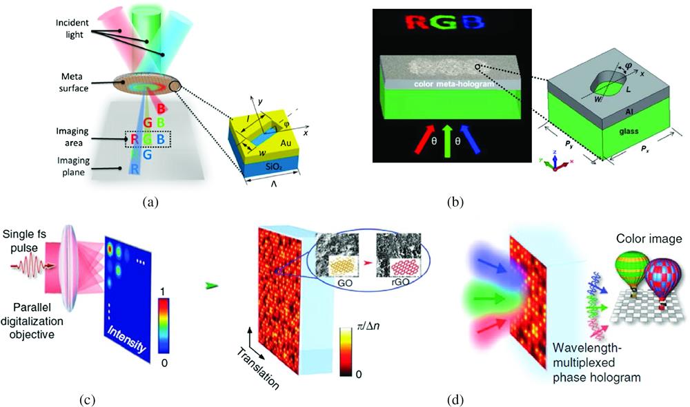
In this section, we discuss multicolor holograms realized by an angular multiplexing method. Li et al. demonstrated this approach with geometric metasurfaces consisting of nanoslits in gold films70 [Fig. 1(a)]. The design process can be summarized as follows. The multicolor target image is first decomposed into R, G, and B components,70 which are to be reconstructed by the R, G, and B laser beams, respectively. The red component is displaced from the original position to the new position . In other words, when the hologram is illuminated by the normally incident laser beam, the reconstructed red image will be located at . However, by adjusting the incident angle, the reconstructed image can be made to be at . The crosstalk images generated by the red laser beam will thus occur at other locations and will be excluded from the observation zone near . Similar processes are carried out for green and blue beams. This results in the observation zone near containing the correct R, G, and B components, with the crosstalk images occurring at other locations (i.e., not in the observation zone). A phase-only hologram corresponding to this target image is then calculated by the Gerchberg–Saxton (GS) algorithm.73 Each sampled phase pixel is then substituted by a nanoslit with a certain orientation angle. When the metasurface is illuminated by R, G, and B laser beams at the designed incident angles, a multicolor holographic image is reconstructed. To further verify the feasibility of this approach, Li et al. experimentally reconstructed an image with seven colors. The method can also be used for 3D holography,70 where a 3D target image is decomposed into a series of points. The superposition of the complex amplitudes of the light emitted from these points comprises a multicolor hologram that generates the 3D image in the Fresnel range. Zhang et al. combined angular multiplexing with polarization-dependent geometric phase to produce two independent multicolor holographic images, one for transmitted light while the other for reflected light.74 Wan et al. demonstrated multicolor holograms with aluminum geometric metasurfaces [Fig. 1(b)] with two amplitude levels and eight phase levels of modulation.71 Amplitude modulation is implemented by pixels that include or omit the nanoslit. Phase is modulated in eight levels (0, , , , , , , ) via (eight different) orientation angles for the nanoslits.

Figure 1.Multicolor holograms that employ angular multiplexing. (a) Multicolor images generated by off-axis illumination of the metasurface hologram. The metasurface consists of nanoslits in a gold film. (b) Multicolor hologram that consists of nanoslits in an aluminum film. (c) Schematic of phase modulation by athermal photoreduction using a single fs pulse. A pulse passes through a parallel digitalization objective and generates a focal spot array with different intensities, which in turn leads to refractive-index modulation of the rGO composite. (d) Multicolor image generated by illuminating the metasurface with R, G, and B beams at different angles. The figures are reproduced with permission from (a) Ref. 70, (b) Ref. 71, (c), (d) Ref. 72.
Nanoslit-based multicolor holograms are polarization sensitive. Li et al. showed that, by contrast, a polarization insensitive multicolor hologram can be realized with reduced graphene-oxide (rGO), obtained via the athermal photoreduction of graphene-oxide using a femtosecond laser.72 The refractive index of the rGO is related to the intensity of the incident light spot [Fig. 1(c)] and is spectrally flat in the visible region. It is, therefore, ideal for multicolor image generation through angular multiplexing. More colors (i.e., beyond R, G, and B), such as yellow and white, can be achieved by adjusting the powers of the R, G, and B laser beams [Fig. 1(d)].
2.1.2 Polarization multiplexing method
As discussed above, angular multiplexing is one way to implement independent R, G, and B channels. Another way of achieving this is via the polarization states of the input/output light. This approach requires the metasurface to comprise a spatially varying arrangement of polarization-modulation elements. Hu et al. demonstrated a metasurface consisting of rectangular nanopillars with different shapes and orientations on an substrate.64 Each nanopillar can be regarded as a linearly birefringent wave plate with a certain orientation angle. The length, width, and orientation angle of the nanopillars vary with position on the metasurface. The design process of the hologram is as follows [Fig. 2(a)]. A multicolor target image is decomposed into R, G, and B components. The sizes of these target image components are scaled to account for the inherent wavelength-dependence of the hologram. In other words, the red component will be made smaller than the green component, while the blue component will be made larger, so that the R, G, and B parts of the reconstructed image are of the same size. The hologram is designed with the GS algorithm, with the Fourier transform as the propagation function. Therefore, if the field of view (FOV) is large, there will be distortion since the design principle makes the paraxial approximation. In other words, a large FOV will make the paraxial approximation imprecise. This distortion can be prevented by appropriate design. After that, the phase profiles of the three components are retrieved and encoded into the three independent polarization channels of the metasurface. One may thus regard the metasurface as storing three types of information in an independent fashion, accessible by different combinations of input/output polarization states [Fig. 2(a)]. Here, when the input/output are - polarized, only the red component of the holographic image is reconstructed. Similarly, the green and blue components correspond to the - and - combinations, respectively. These images in the three channels are selected and combined through the optical setup to form a color holographic vectorial image.
Figure 2.Multicolor holograms by the polarization multiplexing method. (a) Design process for the vectorial color holographic metasurface. (b) Schematic of 6-bit metasurface. Holographic images that result from the state (color and polarization) of the incident light as denoted by codes 010000, 001000, 000100, 000110, 000101, 000011, 111000, and 001110 are shown in the right panel of the image. Figures reproduced with permission from (a) Ref. 64 and (b) Ref. 75.
Instead of controlling the input/output polarization combination, Jin et al. showed a polarization multiplexing method in which only the polarization of the incident light needs to be changed.75 The combination of the three color channels (R/G/B) and the two different helicities results in six channels (red LCP, red RCP, green LCP, green RCP, blue LCP, and blue RCP). The presence or absence of a channel in the incident light denotes the bit being “1” or “0,” respectively. The incident light can thus be thought of as representing the combinations “010000,” “001000,” etc. [Fig. 2(b)]. The metasurface is designed as follows. A hologram consisting of an array of silicon nanobricks is first devised for the red LCP, green LCP, and blue LCP channels, with the goal of producing three independent images at the chosen observation plane (within the Fresnel diffraction region). A second hologram, this time for red RCP, green RCP, and blue RCP channels, is then generated, with the goal to produce another set of independent images at the same observation plane. The two holograms are then combined to form a single metasurface. As a result, it is possible to reconstruct 63 () spin- and wavelength-dependent holographic images by controlling the 6 bits corresponding to the RGB-polarization states of the incident light. It is interesting to notice that, although there are six available channels of incident light, a colorful holographic image can be reconstructed when two or more channels of different colors are used (such as, red LCP and green LCP).76,77
2.2 Multicolor Holograms with Simultaneous Color Filtering and Phase Control Functionalities
2.2.1 Narrow-band CP converters
Although the multiplexing method enables multicolor image generation, a more straightforward and general method involves structures that serve as both nanofilters for color and as phase controlling elements. Wang et al., for example, used three types of silicon nanoblock structures ,78 with each serving as a narrowband half-waveplate [Figs. 3(a) and 3(b)]. Consider the structures illuminated by broadband CP light of a certain helicity (e.g., LCP). In the spectrum of the transmitted light with opposite helicity (e.g., RCP), a peak appears at around 633 nm. Similarly, the peaks of the cross-polarization spectra for and are around 532 and 473 nm, respectively. Due to the fact that these peaks in the cross-polarization spectra are narrow, when a metasurface comprising these nanoblocks is illuminated by a CP laser beam at one of the design wavelengths (e.g., R), scattering of the cross-polarized light from the nanoblocks of the corresponding type ( for this example) is far stronger than from the other types ( and in this example). The authors note that the efficiency for the blocks is lower than that of and . The authors thus have the supercell contain two blue blocks, while just one red block and one green block to balance the total scattering at each wavelength. Each supercell simultaneously provides the desired phases at the three wavelengths. A schematic diagram of multicolor image generation by the metasurface is shown in Fig. 3(c). Laser beams illuminate the metasurface from the substrate side, and the image is observed on the transmission side. Zhao et al. demonstrated that the silicon nanoblocks can also be designed to work in the reflection mode to provide narrow resonance peaks.79 As shown in Fig. 3(d), in this configuration, the reflected color holographic image is collected using a beam splitter. Via similar principles, the concepts used for multicolor hologram can be extended to allow color-tunable holograms.63 In the work of Wang et al. [Fig. 3(e)], a holographic image whose color can be tuned by polarization state is demonstrated. The image consists of a chameleon on a tree branch. The hologram consists of silicon nanoblocks with resonances at red and green wavelengths. The nanoblocks designed for the green generate the tree branch in the holographic image, regardless of incident polarization state. This is realized by designing the hologram to produce the same phase shifts (and thus the same holographic image of the tree branch) for RCP and LCP incident light. The nanoblocks designed for the green also generate a holographic image of a chameleon when illuminated by an LCP green laser beam (). The nanoblocks designed for the red generate a chameleon image only when illuminated by an RCP red laser beam (). When the incident light (i.e., red and green lasers) is varied from RCP to linear to LCP, the color of the chameleon thus changes gradually from red to yellow to green, while the tree branch remains green.
Figure 3.Narrow band CP converters-based multicolor holograms. (a) Solid curves: simulated diffraction efficiency of three nanoblock types, denoted by , , and . The circle, square, and rectangle represent the simulated efficiency when the , , and are merged into the same pixel as shown in (b). (c) Schematic of multicolor image reconstruction. (d) Multicolor hologram in reflection mode. The metasurface consists of three types of silicon nanoblocks that work as narrow band CP converters. (e) Schematic of the polarization-controlled multicolor hologram. The figures are reproduced with permission from (a)–(c) Ref. 78, (d) Ref. 79, and (e) Ref. 63.
The multicolor holograms we have described thus far produce holographic images when illuminated by R, G, and B laser beams. However, the hologram itself can be designed so that it functions as a color printed image when viewed with bright-field illumination. As shown in Fig. 4(a), Zhang et al. showed that shallow plasmonic gratings made from silver can be used for this purpose.80 The grating structure can excite propagating surface plasmons and localized surface plasmons simultaneously, with the former dominating.83 When the incident CP light is away from the resonance, the vast majority of the reflected light from the grating will have helicity opposite to that of the incident light. In this case, the grating functions as a normal mirror. However, when illuminated on resonance, the reflected components parallel and perpendicular to the grating lines have a phase difference. Therefore, most of the reflected light from the grating will have the same helicity as the incident CP light and carries the geometric phase. The resonance is narrow and is determined by the period, width, and depth of the gratings, thereby providing a means for color selection. The gratings can furthermore be patterned to produce a color printed image. In other words, the metasurface exhibits vivid color under illumination by CP white light and with optics used to detect only the reflected light with the same helicity [Fig. 4(b)]. The gratings are oriented such that the metasurface also functions as a hologram. When illuminated with R, G, and B laser beams, a colorful holographic image is produced [Fig. 4(c)]. Wei et al. devised a metasurface consisting of amorphous silicon nanoblocks and nanoblock dimers [Fig. 4(d)]. These show transmission peaks in the green and red regions of the cross-polarization spectrum.81 The nanoblocks and nanoblock dimers are arranged to form a metasurface hologram that also functions as a color printed image [map of the world, Fig. 4(e)] when illuminated with white light. The holographic image is that of a plant [red flower and green leaves, Fig. 4(f)] and produced under illumination by red and green laser beams. Similarly, Yoon et al. showed a crypto-display84 that consists of two sets of dimers, which have different reflectance spectra in the visible range, but the same cross-polarization conversion efficiency at a certain design wavelength (635 nm). A multicolor image of a red “” symbol on a green background is observed under white light illumination, and a monochromatic holographic image containing the value of “” is reconstructed for illumination by a laser with a wavelength of 635 nm.
Figure 4.Color printing and holography by the narrow band CP converters. (a) Schematic of a shallow plasmonic grating. (b) Printed image observed with the white light microscope. This chip would be used with a “decryption device” that ensures that the incident light and the detected light are both CP with the same helicity. (c) Holographic image generated when the chip is illuminated by R, G, and B laser beams. (d) Schematics of a nanoblock (right) and a nanoblock dimer (left), which make up the metasurface. (e) Optical microscope image of the hologram when viewed under white light illumination. (f) Two-color (R & G) holographic image. (g) Unit cell of the metasurface hologram, containing two crystalline silicon nanoblocks. (h) Color printed image (left) and reconstructed holographic image (right). The figures are reproduced with permission from: (a)–(c) Ref. 80; (d)–(f) Ref. 81; (g), (h) Ref. 82.
The favorable attributes of amorphous silicon as a material with which to realize nanoblock-based metasurfaces [Fig. 4(d)] include its high refractive index and the fact that it can be readily deposited by standard microfabrication processes. On the other hand, crystalline silicon presents the opportunity for a higher conversion efficiency at visible wavelengths, as the imaginary component of its complex refractive index is smaller. Figure 4(g) shows the unit cell of the metasurface of Bao et al. that comprises two crystalline silicon nanoblocks.82 The dimensions of the nanoblocks determine the position of the peaks seen in the cross-polarized transmission spectra. For example, for blocks with a pixel size , width , and height , spectral peaks in the cross-polarization transmission spectra occur at B, G, and R wavelengths for block lengths of 80, 110, and 160 nm, respectively. The rotation angles of the two nanoblocks are and , respectively [Fig. 4(g)]. When illuminated by LCP light, the RCP transmitted light from the two blocks can be summed up as , where . Therefore, the intensity and phase of the transmitted RCP light can be controlled by the rotation angles of the two nanoblocks. As a printed color image, the metasurface covers not only the primary R, G, and B colors but also achieves arbitrary hue-saturation brightness [Fig. 4(h)]. As the metasurface achieves independent control over intensity and phase, it can also generate a full-color holographic image.
2.2.2 Dispersion phase-based metasurface
In Sec. 2.2.1, color filtering is achieved via geometric metasurfaces that achieve well-separated peaks in their cross-polarization transmission or reflection spectra, i.e., when converting the incident CP light to CP light of opposite helicity for transmission-type devices and to CP light of the same helicity for reflection-type devices. We next discuss another metasurface type that can also function as both a color printed image and a multicolor hologram, namely the dispersion phase metasurface. In Fig. 5(a), we show the work of Huang et al., who develop a metasurface consisting of an Al--mirror configuration.85 This structure has resonances that span the visible wavelength range as the rod length is varied from 50 to 150 nm. Figure 5(b) shows simulations of the reflectance and of the phase of reflected light versus nanorod length for illumination at three wavelengths that represent B, G, and R, i.e., 405, 532, and 658 nm. This configuration allows two-level phase modulation to be achieved by proper selection of nanorod length. This can be understood as follows. For blue light (i.e., at 405 nm), two nanorods with and provide equal reflectance and a phase difference of , which is ideal for a two-level phase-only hologram. It can be seen that the phase difference between such nanorods is minor for green (532 nm) and red (658 nm), meaning that there will be little crosstalk from the blue channel to the green and red channels. Similarly, the nanorods with and are suitable for the green channel, while and are suitable for the red channel. These nanorods are interleaved to form supercells that contain two red subcells, one green subcell, and one blue subcell. These supercells constitute a multiwavelength hologram, with the reconstructed image shown in Fig. 5(c). It should be noted that a red letter “G” appears near red “R,” which the authors attribute to being the result of resonance overlap of the green subpixels (into the red channel).
Figure 5.Dispersion phase-based multicolor holograms. (a) Simulated reflectance spectra, with the nanorod length varied. (b) Simulated reflectance and phase at , 532, and 658 nm. Blue circles, green triangles, and red squares indicate the nanorod lengths used for the blue, green, and red channels, respectively. (c) Experimentally obtained color holographic image. (d) Unit cell of the multicolor hologram. (e) Calculated phases at wavelengths of 460, 540, and 700 nm. The color used for the data points represents the nanopillar width, as indicated by the colorbar. The star symbol (labeled “A”) represents an example of a target phase point, while the red dot (labeled “B”) represents the nanopillar that is closest to this target. (f) Simulated color holographic image produced by the metasurface. The figures are reproduced with permission from: (a)–(c) Ref. 85, (d)–(f) Ref. 86.
In the example mentioned above, color holographic images are generated using structures with different dimensions that provide the phase delays needed for the R/G/B channels. These structures are interleaved to produce the hologram device. On the other hand, it is possible for a single nanostructure geometry to provide the desired phase delay for the R/G/B channels. Shi et al. demonstrated this via a metasurface based on nanopillars on silver, with a thin spacer [Fig. 5(d)].86 The device operates in reflection mode, which means that the propagation distance per pillar is effectively doubled in comparison with what would occur if it were instead operating in transmission mode. This means that the device thickness can be minimized, which is desirable from a manufacturing standpoint. As the width of the nanopillar is varied, the phases of the reflected light at the three different wavelengths also change [Fig. 5(e)]. It can be seen that the points (resulting from varying the nanopillar width) span a large region of the phase space. To understand the process that would be used for metasurface design, consider the case that the target phases are those represented by the star symbol denoted “A” in Fig. 5(e). It be seen that the point that is denoted “B” is quite close to “A.” In other words, because the data set that results from varying the nanopillar width covers a large region of the phase space, any phase target can be achieved with only a small error. The authors used 460, 540, and 700 nm as examples [Fig. 4(e)], and they fabricated a lens with the same focal distance at the three wavelengths. With the same principle, a multicolor hologram working at 480, 530, and 630 nm is also proposed [Fig. 5(f)].
2.2.3 Detour phase-based metasurface
We next describe another metasurface that acts as both a color printed image and as a hologram, this time based on Mie resonances. It has been experimentally demonstrated that nanoparticles can support resonances at visible wavelengths.87–89 The resonance position (wavelength) is determined by the geometric parameters and the packing density of the nanoparticles. nanoparticles can thus be designed to scatter strongly at wavelengths corresponding to R, G, and B. One can thus realize a color printed image by including nanoparticles of the appropriate geometric parameters and packing density so that each part of the metasurface achieves the desired color. The metasurface can furthermore simultaneously function as a hologram via the detour phase concept,90–92 i.e., with the nanoparticle arrays [Figs. 6(a) and 6(b)] being displaced in each pixel to achieve the desired phase.66 Optical microscope images of a fabricated metasurface are shown in Figs. 6(c) and 6(d) and demonstrate the color printed image functionality. The multicolor holographic image produced by illumination of the metasurface with R, G, and B laser beams is shown in Fig. 6(e). To further demonstrate the flexibility of this technique, Wen et al. showed that two different target holography images [Figs. 6(e) and 6(f)] can be encoded into color printed images with very similar appearances. This approach is different from previously demonstrated color printed images or holograms and presents opportunities for optical document security and data storage applications.
Figure 6.Detour phase-based metasurface consisting of color holograms encoded into color printed images. (a) Schematic of a nanocone array that comprises the metasurface. Each cone has height , period , top radius , and taper angle . (b) Illustration of the detour phase concept. Each supercell has width and length . is the distance of the cone array from the supercell center. The detour phase of each pixel is controlled by . (c), (d) Optical image of the metasurface captured by the polarization microscope. The outer diameter of the pattern in (c) is 1.5 mm. The scalebar in (d) represents . (e) Reconstructed holographic image with sample A, whose optical image is shown in (c). (f) Reconstructed holographic image with sample B, whose optical image is similar to (c). Color bars in (e) and (f) both represent 5 cm. The figures are reproduced with permission from (a)–(f) Ref. 66.
2.3 Monolithically Integrated Metasurfaces
In this section, we discuss a monolithic integration approach to metasurfaces in which they consist of two layers of nanostructures. One layer functions as a phase-only hologram while the other serves as a color filter. Although the hologram works for a broad range of wavelengths, the narrow transmission peaks of the color filter will eliminate the crosstalk images. Lim et al. demonstrate the fabrication of nanopillar-type color filters on thin layers referred to as “phase plates” [Fig. 7(a)] via a single lithographic process by 3D direct laser writing on glass substrates.65 The height, diameter, and pitch of the nanopillars are chosen so that it only transmits certain wavelengths. The thickness of the phase plate determines the phase of the transmitted light. As the phase plate and the glass substrate have different refractive indices, varying the phase plate thickness modifies the transmittance (in addition to modifying the phase). To minimize this effect, the minimum thickness of the phase plate is chosen to be (rather than zero thickness). Lim et al. demonstrated that nanopillars allow many colors to be generated in the color printed image [Fig. 7(b)]. The holographic image is still a three-color multiplexed RGB type [Figs. 7(c)–7(e)].
Figure 7.Monolithically integrated metasurfaces that consist of a color filter layer and a phase-only hologram layer. (a) Schematic of the pixel that functions as both a color filter (via nanopillars) and as a phase plate (via thin film under the pillars). (b) Transmission optical micrograph of a color printed image. It contains six colors: red, green, blue, orange, yellow, and purple. (c)–(e) Holographic images produced by illumination with R, G, and B laser beams. (f) Schematic of a metasurface unit cell. The Ag-HSQ-Ag cavity serves as a transmission-type color filter. PMMA nanoholes control the phase of transmitted light. The PMMA layer is separated from the color filter by an HSQ layer. (g) Simulated and experimentally measured transmission spectra of R, G, and B color filters. These are optimized for operation at 450, 532, and 633 nm. The solid/dashed darker blue curves represent experimental/theoretical transmission spectra when the Ag layers (both top and bottom Ag layers in MIM filter) are 26 nm and the total filter height is 93 nm. The thickness of the Ag layer and the height of the structure are listed for the other cases: (darker green curves), (darker red curves), (lighter blue curves), 31 nm/128 nm (lighter green curves), and (lighter red curves). (h) Color holographic image produced by illumination of metasurface with R, G and B laser beams. The image is of James Clerk Maxwell, with the different colors achieved via mixtures of R, G, B components. The figures are reproduced with permission from: (a)–(e) Ref. 65, (f)–(h) Ref. 93.
In this section, we consider metasurfaces in which the phase-only hologram and the color filter are two separate devices. There are thus a variety of structures, in addition to the nanopillars discussed above, that can be used to realize the color filters. It is well known that Fabry–Pérot cavities can be used as narrowband filters.94 Hu et al. demonstrated that micrometal/insulator/metal (MIM) Fabry–Pérot cavity resonators with varied dielectric thickness can provide a high efficiency and narrow bandwidth in the visible range, which is beneficial for suppressing crosstalk in multicolor holograms.93Figure 7(f) schematically illustrates the unit cell of this metasurface, which functions as both a color printed image and a multicolor hologram.93 An Ag-hydrogen silsesquioxane (HSQ)-Ag cavity is formed on a quartz substrate. The bottom Ag layer acts as a semireflective film, which enables the device to work in transmission mode, i.e., the light shines from the quartz substrate side, then passes through the MIM cavity and the hologram sequentially. The transmittance of the color filter is related to the thickness of the Ag layer, and the position of the resonance peak is controlled by the thickness of the HSQ [Fig. 7(g)]. One can thus achieve the desired color via grayscale lithography. A color printed image containing Einstein’s mass-energy equation image is achieved by arranging these color filters. This image is shown in the original paper93 and not provided here due to space constraints. A PMMA layer on top of the device is used to control the phase of the transmitted light and thus enable the hologram functionality. This phase control is achieved by varying the width of the (square) nanoholes, which determines the effective refractive index of this layer. Holographic images with yellow, purple, and cyan colors can be obtained by mixing the R, G, and B channels [Fig. 7(h)].
2.4 Binary/Complex Amplitude Modulation
As reviewed in Secs. 2.1–2.4, at the time of writing, the multicolor metasurface holograms that have been demonstrated have usually employed phase-only modulation. Holographic multicolor images, however, can be implemented via amplitude modulation. Montelongo et al. demonstrated this approach via a metasurface that contains two types of silver nanoparticles [Fig. 8(a)].96 The nanoparticles with circular shapes (diameter: 60 nm) have a localized surface plasmon resonance in the blue region. The elliptical nanoparticles (width: 60 nm, length: 165 nm) have two resonances when excited by illumination polarized along the axes of the ellipses. The scattering peaks at short and long wavelengths correspond to the localized surface plasmon resonances at the top of the particle and at the Ag/substrate interface, respectively.98 The metasurface produces one holographic image (A) when illuminated by blue light and another holographic image (B) for red light. The operating principle is as follows. Image “A” is produced for blue light via an amplitude modulation hologram implemented by the presence or absence of the circular particles. Similarly, image “B” is encoded by the elliptical nanoparticles, again via amplitude modulation. We would like this image to be produced in response to red light only. To achieve this, the authors place a pair of nanospheres at each location in hologram B for which a nanorod is missing. This modifies the diffraction pattern that occurs with blue light as there are blue light scatterers in each pixel of hologram B. The red diffraction remains unchanged because it still has amplitude modulation. As a result, hologram B will scatter the red laser beam and form an image with little blue crosstalk. The two holograms are interleaved and reconstruct a two-color image [Fig. 8(b)].
Figure 8.Multicolor holograms realized with binary/complex amplitude modulation. (a) Design process for a multicolor hologram consisting of circularly and elliptically shaped silver particles. (b) Two-color holographic image produced by illumination of a metasurface with red and blue laser beams. (c) Schematic of a metasurface waveguide system. R, G, and B laser beams are coupled into a waveguide by a grating coupler. (d) Holographic image produced by a metasurface waveguide system. R, G, and B light in waveguides is coupled out into free space by the grating-based metasurface to form the holographic image. (e) Unit cell of the device termed a “multifreedom metasurface” by Deng et al.95 Amplitude, phase, and polarization of the reflected light can be controlled by the parameters , , , and . (f) Simulated (left) and experimentally obtained (right) holographic images. The figures are reproduced with permission from (a), (b) Ref. 96, (c), (d) Ref. 97, (e), (f) Ref. 95.
The multicolor metasurface holograms discussed thus far produce holographic images when illuminated by R, G, and B laser beams in free space. The use of waveguide, rather than free space, excitation presents the opportunity to make the system even more compact and more robust to misalignment. Huang et al. demonstrated this approach via a waveguide that comprises a layer of the electron beam lithography resist ZEP [Fig. 8(c), 300 nm thick].97 With the grating periods and incident angles chosen appropriately, R, G, and B laser beams from free space are coupled into the waveguide. As the waveguide is planar-type (e.g., rather than a strip- or ridge-type), the guided light spreads as it propagates. As the light encounters the binary amplitude metasurface, it is coupled back into free space, producing a multicolor holographic image [Fig. 8(d)]. Deng et al. demonstrated another metasurface approach that combines geometric phase and detour phase in a diatomic design, as shown in Fig. 8(e).95 The authors use an MIM type metasurface that consists of an Al layer (130 nm thick) on an Si substrate, an spacer layer (100 nm thick), and an array of Al nanorod (30 nm thick). Each unit cell has a width of and contains two ellipses. We denote the positions of the latter by and . The orientations are denoted by and . The incident angle (60 deg) and polarization (-) of the incident beam are chosen to make most of the reflected energy be in the first order. When the sample is illuminated by -polarized light at an incident angle of 60 deg, the reflected light in the first order becomes . We have and . As a result, the metasurface can simultaneously and independently modulate the phase, polarization, and amplitude of the reflected beam if the four degrees of freedom are fully employed. The expressions for the phase/amplitude/polarization terms are derived from the expression for and labeled in Fig. 8(e). To design the multicolor hologram, the target image is first decomposed into R, G, and B components. The standard Fresnel diffraction formulas are then used to calculate the complex amplitudes of the R, G, and B holograms. However, the reconstructed R, G, and B images will be at different diffraction angles, i.e., there will be angular dispersion (like a grating that separates different wavelengths). Therefore, these holograms are added with phase shift factors of , , and , respectively, to compensate the angular dispersion to ensure that the R, G, and B images are reconstructed at the same area. The complex amplitudes of the R, G, and B holograms are summed up to form a new hologram. For -polarized illumination of the metasurface at an incident angle of 60 deg, a multicolor image is reconstructed [Fig. 8(f)]. Benefiting from the flexible polarization control ability, two sets of metamolecules that correspond to different input/output polarization states are interleaved to form a new hologram (the odd and even metamolecule rows in the hologram correspond to different input/output polarization states). The first type metamolecules reconstruct a color image A when the incident/output light is or polarized, and the second type metamolecules reconstruct image B when the incident/output light is or polarized.
3 Conclusion
In this paper, we have reviewed recent developments in metasurface-based multicolor holograms. Let us conclude by first reiterating our summary of the status of the field at the time of writing and then by discussing future prospects. As discussed, one may classify metasurface-based multicolor holograms into four categories. The first are those that do not perform color filtering, with angular multiplexing used to generate the desired image at the design location. Alternatively, polarization multiplexing can be used to link RGB color information with different input/output polarization states. In the second category, the nanostructures of the metasurface are used to simultaneously perform color filtering and phase control. In the third category, monolithically integrated metasurfaces are realized in which one layer comprises the phase-only hologram and another layer comprises color filters. The fourth category that we consider is intensity/complex amplitude holograms that generate multicolor images. We imagine that it has been evident to the reader that, at the time of writing, the key issue is how to eliminate crosstalk between different colors. While impressive demonstrations have been made of metasurface color holograms, we contend that there is still much to be done. Currently, multicolor holographic images generated by metasurfaces are generally static. One might expect that the ability to dynamically reconfigure these holographic images would open the door to numerous applications. Shallow plasmonic gratings,83 or dielectric nanoparticles supporting Mie resonance,99,100 can be used to generate spectral peaks (in reflection) that shift as the refractive index of the surrounding medium is modified. The scattering properties of nanostructures can also be modified by lasers with short pulses (e.g., picoseconds),101 by field effects,102 by heat,103 or by mechanical forces.104
Recently, a nonlinear transition metal dichalcogenide hologram, using a patterned tungsten disulfide (WS2) monolayer, has been experimentally demonstrated.105 The generated second harmonic (from NIR to visible) can change its color with the pump light.106 We anticipate that investigation of these and other mechanisms for reconfigurable color holograms will be good avenues for future research. At the time of writing, display technologies represent a ubiquitous component of personal electronic devices, such as smartphones, tablets, and laptops. One can imagine that users might welcome the incorporation of projectors into such devices as these would allow large images to be viewed (e.g., on a wall) despite the device itself being small. A multicolor metasurface that can be dynamically reconfigured in some respects represents the ultimate in projector miniaturization, especially if the light sources are integrated (e.g., via waveguides or by light-emitting pixels). Even more exciting would be a multicolor metasurface hologram that produces 3D images that can be dynamically reconfigured. While we have some way to go to achieve this goal, its realization could enable a real leap in human–computer interactions. It is also reasonable to expect that there would be numerous applications for the intermediate advances and discoveries that would occur along the way. With its interesting blend of Fourier optics, nano-optics, and materials science, and the prospect of real-world technological applications, we expect that the field of metasurface-based multicolor holograms will be a fertile ground for some years to come.
References
[1] D. Gabor. Microscopy by reconstructed wave-fronts. Proc. R. Soc. London A, 197, 454-487(1949).
[2] P. Hariharan. Basics of Holography(2002).
[3] J. Upatnieks, J. Marks, R. Fedorowicz. Color holograms for white light reconstruction. Appl. Phys. Lett., 8, 286-287(1966).
[4] H. Chen, F. T. Yu. One-step rainbow hologram. Opt. Lett., 2, 85-87(1978).
[5] F. Yu, G. Gerhart. White light transmission color holography: a review. Opt. Eng., 24, 245812(1985).
[6] M. Ozaki, J.-I. Kato, S. Kawata. Surface-plasmon holography with white-light illumination. Science, 332, 218-220(2011).
[7] N. Yu et al. Light propagation with phase discontinuities: generalized laws of reflection and refraction. Science, 334, 333-337(2011).
[8] G. Zheng et al. Metasurface holograms reaching 80% efficiency. Nat. Nanotechnol., 10, 308-312(2015).
[9] D. Lin et al. Dielectric gradient metasurface optical elements. Science, 345, 298-302(2014).
[10] X. Ni, A. V. Kildishev, V. M. Shalaev. Metasurface holograms for visible light. Nat. Commun., 4, 2807(2013).
[11] R. J. Lin et al. Achromatic metalens array for full-colour light-field imaging. Nat. Nanotechnol., 14, 227-231(2019).
[12] Z. Yang et al. Generalized Hartmann-Shack array of dielectric metalens sub-arrays for polarimetric beam profiling. Nat. Commun., 9, 4607(2018).
[13] L. Wang et al. Grayscale transparent metasurface holograms. Optica, 3, 1504-1505(2016).
[14] E. Schonbrun, K. Seo, K. B. Crozier. Reconfigurable imaging systems using elliptical nanowires. Nano Lett., 11, 4299-4303(2011).
[15] S.-Q. Li et al. Generalized method of images and reflective color generation from ultrathin multipole resonators. ACS Photonics, 5, 2374-2383(2018).
[16] D. J. Roth et al. 3D full-color image projection based on reflective metasurfaces under incoherent illumination. Nano Lett., 20, 4481-4486(2020).
[17] S. Chang, X. Guo, X. Ni. Optical metasurfaces: progress and applications. Annu. Rev. Mater. Res., 48, 279-302(2018).
[18] G. Y. Lee, J. Sung, B. Lee. Recent advances in metasurface hologram technologies. ETRI J., 41, 10-22(2019).
[19] F. Ding, A. Pors, S. I. Bozhevolnyi. Gradient metasurfaces: a review of fundamentals and applications. Rep. Prog. Phys., 81, 026401(2018).
[20] S. A. Maier. Plasmonics: Fundamentals and Applications(2007).
[21] M. Kim, A. M. H. Wong, G. V. Eleftheriades. Optical Huygens’ metasurfaces with independent control of the magnitude and phase of the local reflection coefficients. Phys. Rev. X, 4, 041042(2014).
[22] C. Pfeiffer et al. Efficient light bending with isotropic metamaterial Huygens’ surfaces. Nano Lett., 14, 2491-2497(2014).
[23] F. Aieta et al. Aberration-free ultrathin flat lenses and axicons at telecom wavelengths based on plasmonic metasurfaces. Nano Lett., 12, 4932-4936(2012).
[24] F. Ding, R. Deshpande, S. I. Bozhevolnyi. Bifunctional gap-plasmon metasurfaces for visible light: polarization-controlled unidirectional surface plasmon excitation and beam steering at normal incidence. Light Sci. Appl., 7, 17178(2018).
[25] W. T. Chen et al. High-efficiency broadband meta-hologram with polarization-controlled dual images. Nano Lett., 14, 225-230(2014).
[26] A. Zhan et al. Low-contrast dielectric metasurface optics. ACS Photonics, 3, 209-214(2016).
[27] J. S. Park et al. All-glass, large metalens at visible wavelength using deep-ultraviolet projection lithography. Nano Lett., 19, 8673-8682(2019).
[28] A. Arbabi et al. Dielectric metasurfaces for complete control of phase and polarization with subwavelength spatial resolution and high transmission. Nat. Nanotechnol., 10, 937-943(2015).
[29] E. Arbabi et al. Multiwavelength polarization-insensitive lenses based on dielectric metasurfaces with meta-molecules. Optica, 3, 628-633(2016).
[30] P. Gutruf et al. Mechanically tunable dielectric resonator metasurfaces at visible frequencies. ACS Nano, 10, 133-141(2016).
[31] A. Forouzmand, H. Mosallaei. Dynamic beam control via Mie-resonance based phase-change metasurface: a theoretical investigation. Opt. Express, 26, 17948-17963(2018).
[32] A. I. Kuznetsov et al. Optically resonant dielectric nanostructures. Science, 354, aag2472(2016).
[33] Q. L. Yang et al. Mie-resonant membrane Huygens’ metasurfaces. Adv. Funct. Mater., 30, 1906851(2020).
[34] A. Leitis et al. All-dielectric programmable Huygens’ metasurfaces. Adv. Funct. Mater., 30, 1910259(2020).
[35] D. Arslan et al. Angle-selective all-dielectric Huygens’ metasurfaces. J. Phys. D Appl. Phys., 50, 434002(2017).
[36] W. Y. Zhao et al. Dielectric Huygens’ metasurface for high-efficiency hologram operating in transmission mode. Sci. Rep., 6, 30613(2016).
[37] S. Pancharatnam. Generalized theory of interference and its applications. Proc. Indian Acad. Sci. Sec. A, 44, 398-417(1956).
[38] M. V. Berry. Quantal phase factors accompanying adiabatic changes. Proc. R. Soc. London A, 392, 45-57(1984).
[39] Z. E. Bomzon et al. Space-variant Pancharatnam–Berry phase optical elements with computer-generated subwavelength gratings. Opt. Lett., 27, 1141-1143(2002).
[40] F. Yue et al. High-resolution grayscale image hidden in a laser beam. Light Sci. Appl., 7, 17129(2018).
[41] G. Y. Lee et al. Metasurface eyepiece for augmented reality. Nat. Commun., 9, 4562(2018).
[42] F. Y. Yue et al. Highly sensitive polarization rotation measurement through a high-order vector beam generated by a metasurface. Adv. Mater. Technol., 5, 1901008(2020).
[43] D. Wen et al. Helicity multiplexed broadband metasurface holograms. Nat. Commun., 6, 8241(2015).
[44] J. Deng et al. Spatial frequency multiplexed meta-holography and meta-nanoprinting. ACS Nano, 13, 9237-9246(2019).
[45] Q. Wei et al. Broadband multiplane holography based on plasmonic metasurface. Adv. Opt. Mater., 5, 1700434(2017).
[46] K. Huang et al. Silicon multi‐meta‐holograms for the broadband visible light. Laser Photonics Rev., 10, 500-509(2016).
[47] S. Choudhury et al. Pancharatnam-berry phase manipulating metasurface for visible color hologram based on low loss silver thin film. Adv. Opt. Mater., 5, 1700196(2017).
[48] C. Choi et al. Hybrid state engineering of phase-change metasurface for all-optical cryptography. Adv. Funct. Mater., 31, 2007210(2020).
[49] Q. Wang et al. All-dielectric meta-holograms with holographic images transforming longitudinally. ACS Photonics, 5, 599-606(2018).
[50] H. R. Ren et al. Complex-amplitude metasurface-based orbital angular momentum holography in momentum space. Nat. Nanotechnol., 15, 948-955(2020).
[51] X. J. Ni, A. V. Kildishev, V. M. Shalaev. Metasurface holograms for visible light. Nat. Commun., 4, 2807(2013).
[52] L. Liu et al. Broadband metasurfaces with simultaneous control of phase and amplitude. Adv. Mater., 26, 5031-5036(2014).
[53] G. Y. Lee et al. Complete amplitude and phase control of light using broadband holographic metasurfaces. Nanoscale, 10, 4237-4245(2018).
[54] K. E. Chong et al. Efficient polarization-insensitive complex wavefront control using Huygens’ metasurfaces based on dielectric resonant meta-atoms. ACS Photonics, 3, 514-519(2016).
[55] M. Fratz, P. Fischer, D. M. Giel. Full phase and amplitude control in computer-generated holography. Opt. Lett., 34, 3659-3661(2009).
[56] M. Fratz, D. M. Giel, P. Fischer. Digital polarization holograms with defined magnitude and orientation of each pixel’s birefringence. Opt. Lett., 34, 1270-1272(2009).
[57] L. Huang et al. Three-dimensional optical holography using a plasmonic metasurface. Nat. Commun., 4, 2808(2013).
[58] G. Li, S. Zhang, T. Zentgraf. Nonlinear photonic metasurfaces. Nat. Rev. Mater., 2, 17010(2017).
[59] F. Walter et al. Ultrathin nonlinear metasurface for optical image encoding. Nano Lett., 17, 3171-3175(2017).
[60] Z.-L. Deng et al. Diatomic metasurface for vectorial holography. Nano Lett., 18, 2885-2892(2018).
[61] R. Zhao et al. Multichannel vectorial holographic display and encryption. Light Sci. Appl., 7, 95(2018).
[62] E. Arbabi et al. Vectorial holograms with a dielectric metasurface: ultimate polarization pattern generation. ACS Photonics, 6, 2712-2718(2019).
[63] B. Wang et al. Polarization-controlled color-tunable holograms with dielectric metasurfaces. Optica, 4, 1368-1371(2017).
[64] Y. Hu et al. Trichromatic and tripolarization-channel holography with noninterleaved dielectric metasurface. Nano Lett., 20, 994-1002(2019).
[65] K. T. Lim et al. Holographic colour prints for enhanced optical security by combined phase and amplitude control. Nat. Commun., 10, 25(2019).
[66] D. Wen et al. Multifunctional dielectric metasurfaces consisting of color holograms encoded into color printed images. Adv. Funct. Mater., 30, 1906415(2020).
[67] B. Walther et al. Spatial and spectral light shaping with metamaterials. Adv. Mater., 24, 6300-6304(2012).
[68] Q. Wang et al. Polarization and frequency multiplexed terahertz meta‐holography. Adv. Opt. Mater., 5, 1700277(2017).
[69] A. C. Overvig et al. Dielectric metasurfaces for complete and independent control of the optical amplitude and phase. Light Sci. Appl., 8, 92(2019).
[70] X. Li et al. Multicolor 3D meta-holography by broadband plasmonic modulation. Sci. Adv., 2, e1601102(2016).
[71] W. Wan, J. Gao, X. Yang. Full-color plasmonic metasurface holograms. ACS Nano, 10, 10671-10680(2016).
[72] X. Li et al. Athermally photoreduced graphene oxides for three-dimensional holographic images. Nat. Commun., 6, 6984(2015).
[73] R. W. Gerchberg, W. O. Saxton. A practical algorithm for the determination of phase from image and diffraction plane pictures. Optik, 35, 237-246(1972).
[74] X. Zhang et al. Colorful metahologram with independently controlled images in transmission and reflection spaces. Adv. Funct. Mater., 29, 1809145(2019).
[75] L. Jin et al. Noninterleaved metasurface for (26-1) spin-and wavelength-encoded holograms. Nano Lett., 18, 8016-8024(2018).
[76] L. Jin et al. Dielectric multi-momentum meta-transformer in the visible. Nat. Commun., 10, 4789(2019).
[77] F. Qin et al. Broadband full-color multichannel hologram with geometric metasurface. Opt. Express, 26, 11577-11586(2018).
[78] B. Wang et al. Visible-frequency dielectric metasurfaces for multiwavelength achromatic and highly dispersive holograms. Nano Lett., 16, 5235-5240(2016).
[79] W. Zhao et al. Full-color hologram using spatial multiplexing of dielectric metasurface. Opt. Lett., 41, 147-150(2016).
[80] F. Zhang et al. Simultaneous full‐color printing and holography enabled by centimeter‐scale plasmonic metasurfaces. Adv. Sci., 7, 1903156(2020).
[81] Q. Wei et al. Simultaneous spectral and spatial modulation for color printing and holography using all-dielectric metasurfaces. Nano Lett., 19, 8964-8971(2019).
[82] Y. Bao et al. Full-colour nanoprint-hologram synchronous metasurface with arbitrary hue-saturation-brightness control. Light Sci. Appl., 8, 95(2019).
[83] M. Song et al. Color display and encryption with a plasmonic polarizing metamirror. Nanophotonics, 7, 323-331(2018).
[84] G. Yoon et al. Crypto-display’ in dual-mode metasurfaces by simultaneous control of phase and spectral responses. ACS Nano, 12, 6421-6428(2018).
[85] Y.-W. Huang et al. Aluminum plasmonic multicolor meta-hologram. Nano Lett., 15, 3122-3127(2015).
[86] Z. Shi et al. Single-layer metasurface with controllable multiwavelength functions. Nano Lett., 18, 2420-2427(2018).
[87] S. Sun et al. All-dielectric full-color printing with TiO2 metasurfaces. ACS Nano, 11, 4445-4452(2017). https://doi.org/10.1021/acsnano.7b00415
[88] B. Yang et al. Polarization-sensitive structural colors with hue-and-saturation tuning based on all-dielectric nanopixels. Adv. Opt. Mater., 6, 1701009(2018).
[89] I. Koirala, S.-S. Lee, D.-Y. Choi. Highly transmissive subtractive color filters based on an all-dielectric metasurface incorporating TiO2 nanopillars. Opt. Express, 26, 18320-18330(2018). https://doi.org/10.1364/OE.26.018320
[90] Z. Xie et al. Meta-holograms with full parameter control of wavefront over a 1000 nm bandwidth. ACS Photonics, 4, 2158-2164(2017).
[91] C. Min et al. Plasmonic nano‐slits assisted polarization selective detour phase meta‐hologram. Laser Photonics Rev., 10, 978-985(2016).
[92] M. Khorasaninejad et al. Broadband and chiral binary dielectric meta-holograms. Sci. Adv., 2, e1501258(2016).
[93] Y. Hu et al. 3D-integrated metasurfaces for full-colour holography. Light Sci. Appl., 8, 86(2019).
[94] J. S. Milne et al. Widely tunable MEMS-based Fabry–Perot filter. J. Microelectromech. Syst., 18, 905-913(2009).
[95] Z. L. Deng et al. Full-color complex-amplitude vectorial holograms based on multi-freedom metasurfaces. Adv. Funct. Mater., 30, 1910610(2020).
[96] Y. Montelongo et al. Plasmonic nanoparticle scattering for color holograms. Proc. Natl. Acad. Sci. U. S. A., 111, 12679-12683(2014).
[97] Z. Huang, D. L. Marks, D. R. Smith. Out-of-plane computer-generated multicolor waveguide holography. Optica, 6, 119-124(2019).
[98] F. Beck et al. Resonant SPP modes supported by discrete metal nanoparticles on high-index substrates. Opt. Express, 19, A146-A156(2011).
[99] S. Sun et al. Real-time tunable colors from microfluidic reconfigurable all-dielectric metasurfaces. ACS Nano, 12, 2151-2159(2018).
[100] J. Bohn et al. Active tuning of spontaneous emission by Mie-resonant dielectric metasurfaces. Nano Lett., 18, 3461-3465(2018).
[101] M. R. Shcherbakov et al. Ultrafast all-optical tuning of direct-gap semiconductor metasurfaces. Nat. Commun., 8, 17(2017).
[102] Y.-W. Huang et al. Gate-tunable conducting oxide metasurfaces. Nano Lett., 16, 5319-5325(2016).
[103] N. A. Butakov et al. Broadband electrically tunable dielectric resonators using metal–insulator transitions. ACS Photonics, 5, 4056-4060(2018).
[104] L. Zhu et al. Flexible photonic metastructures for tunable coloration. Optica, 2, 255-258(2015).
[105] A. Dasgupta, J. Gao, X. Yang. Atomically thin nonlinear transition metal dichalcogenide holograms. Nano Lett., 19, 6511-6516(2019).
[106] A. Dasgupta, X. Yang, J. Gao. Nonlinear beam shaping with binary phase modulation on patterned WS2 monolayer. ACS Photonics, 7, 2506-2514(2020).