• Photonics Research
  • Vol. 7, Issue 1, 80 (2019)
Yueyi Yuan1, Kuang Zhang1、2、*, Xumin Ding1、2、4, Badreddine Ratni3, Shah Nawaz Burokur3、5, and Qun Wu1
Author Affiliations
  • 1Department of Microwave Engineering, Harbin Institute of Technology, Harbin 150001, China
  • 2State Key Laboratory of Millimeter Waves, Nanjing 210096, China
  • 3LEME, UPL, Université Paris Nanterre, F92410 Ville d’Avray, France
  • 4e-mail: g0302dxm@163.com
  • 5e-mail: sburokur@parisnanterre.fr
  • show less
    DOI: 10.1364/PRJ.7.000080 Cite this Article Set citation alerts
    Yueyi Yuan, Kuang Zhang, Xumin Ding, Badreddine Ratni, Shah Nawaz Burokur, Qun Wu. Complementary transmissive ultra-thin meta-deflectors for broadband polarization-independent refractions in the microwave region[J]. Photonics Research, 2019, 7(1): 80 Copy Citation Text show less
    Schematic demonstration of a meta-deflector refracting transmitted wave with orthogonal polarization states into arbitrary and asymmetrical directions.
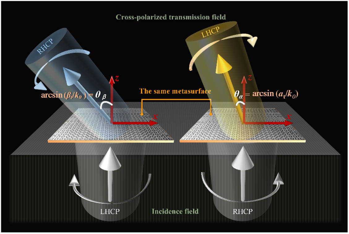
    Fig. 1. Schematic demonstration of a meta-deflector refracting transmitted wave with orthogonal polarization states into arbitrary and asymmetrical directions.
    (a) Schematic of the proposed polarization-controlled refraction meta-deflector; inset shows the unit cell structure with the lattice period a=10 mm, width of slot w=0.2 mm, and gap length g=0.2 mm, and the thickness of the substrate with relative permittivity ϵr=4 is h=2 mm. Simulated transmission (b) amplitude spectra and (c) phase spectra of the unit cell with l1=5.5 mm and l2=6.9 mm. Simulated transmission (d) amplitude Txx and (e) phase delay φxx along the x direction, and transmission (f) amplitude Tyy and (g) phase delay φyy along the y direction as functions of two side lengths l1 and l2 changing from 3.5 mm to 7.0 mm with the other geometric parameters fixed. (h) Simulated phase delay φxx and φyy corresponding to the white dotted lined in (e) and (g), respectively.
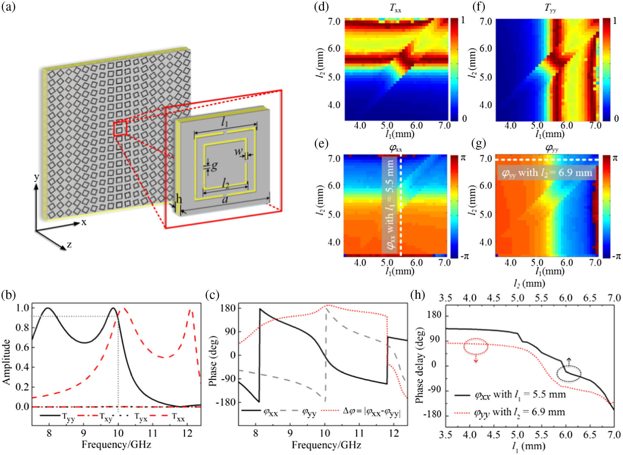
    Fig. 2. (a) Schematic of the proposed polarization-controlled refraction meta-deflector; inset shows the unit cell structure with the lattice period a=10  mm, width of slot w=0.2  mm, and gap length g=0.2  mm, and the thickness of the substrate with relative permittivity ϵr=4 is h=2  mm. Simulated transmission (b) amplitude spectra and (c) phase spectra of the unit cell with l1=5.5  mm and l2=6.9  mm. Simulated transmission (d) amplitude Txx and (e) phase delay φxx along the x direction, and transmission (f) amplitude Tyy and (g) phase delay φyy along the y direction as functions of two side lengths l1 and l2 changing from 3.5 mm to 7.0 mm with the other geometric parameters fixed. (h) Simulated phase delay φxx and φyy corresponding to the white dotted lined in (e) and (g), respectively.
    Design of meta-deflectors for realizing polarized-independent refractions. (a) Schematic of the traditional deflector based on only geometric phase. Schematics of designed (b) meta-deflector 1 and (c) meta-deflector 2 for polarization-independent arbitrary refraction of the transmitted wave without symmetry for two opposite handednesses. Calculated phase delay δx, δy and rotation angle θ as functions of the coordinate of the unit cell along the x direction for (d) meta-deflector 1 and (e) meta-deflector 2. Simulation results of transmitted phase delay φxx, φyy and difference Δφ for collected unit cells for (f) meta-deflector 1 and (g) meta-deflector 2.
    Fig. 3. Design of meta-deflectors for realizing polarized-independent refractions. (a) Schematic of the traditional deflector based on only geometric phase. Schematics of designed (b) meta-deflector 1 and (c) meta-deflector 2 for polarization-independent arbitrary refraction of the transmitted wave without symmetry for two opposite handednesses. Calculated phase delay δx, δy and rotation angle θ as functions of the coordinate of the unit cell along the x direction for (d) meta-deflector 1 and (e) meta-deflector 2. Simulation results of transmitted phase delay φxx, φyy and difference Δφ for collected unit cells for (f) meta-deflector 1 and (g) meta-deflector 2.
    (a) Schematic of the experimental setup for far-field measurement. Photographs of fabricated (b) meta-deflector 1 and (c) meta-deflector 2 (top views); insets are enlarged illustrations of corresponding super cells. (d)–(k) Simulation and measurement results of transmitted cross-polarized waves emitted from meta-deflectors 1 and 2. For meta-deflector 1, (d) and (e) show simulated phase fronts of cross-polarized components in the transmitted field under RHCP and LHCP incidence. (f) and (g) show measured far-field distributions of cross-polarized components in the transmitted field under RHCP and LHCP incidence. For meta-deflector 2, (h) and (i) show simulated phase fronts of cross-polarized components in the transmitted field under RHCP and LHCP incidence. (j) and (k) show far-field distributions of cross-polarized components in the transmitted field under RHCP and LHCP incidence.
    Fig. 4. (a) Schematic of the experimental setup for far-field measurement. Photographs of fabricated (b) meta-deflector 1 and (c) meta-deflector 2 (top views); insets are enlarged illustrations of corresponding super cells. (d)–(k) Simulation and measurement results of transmitted cross-polarized waves emitted from meta-deflectors 1 and 2. For meta-deflector 1, (d) and (e) show simulated phase fronts of cross-polarized components in the transmitted field under RHCP and LHCP incidence. (f) and (g) show measured far-field distributions of cross-polarized components in the transmitted field under RHCP and LHCP incidence. For meta-deflector 2, (h) and (i) show simulated phase fronts of cross-polarized components in the transmitted field under RHCP and LHCP incidence. (j) and (k) show far-field distributions of cross-polarized components in the transmitted field under RHCP and LHCP incidence.
    Simulated and measured efficiencies of proposed meta-deflectors under opposite circularly polarized incidences. Transmission efficiencies of (a) meta-deflector 1 and (b) meta-deflector 2. Conversion efficiencies of (c) meta-deflector 1 and (d) meta-deflector 2. Black-thick lines represent LHCP incidence, while red-fine lines are for RHCP incidence; solid lines indicate measured efficiency, while dashed lines express simulated efficiency.
    Fig. 5. Simulated and measured efficiencies of proposed meta-deflectors under opposite circularly polarized incidences. Transmission efficiencies of (a) meta-deflector 1 and (b) meta-deflector 2. Conversion efficiencies of (c) meta-deflector 1 and (d) meta-deflector 2. Black-thick lines represent LHCP incidence, while red-fine lines are for RHCP incidence; solid lines indicate measured efficiency, while dashed lines express simulated efficiency.
    Unit Cell No.12345678
    l1 (mm)5.55.34.77.06.96.76.25.7
    l2 (mm)6.96.76.25.75.55.34.77.0
    Table 1. Geometric Parameters of Selected Unit Cells for Meta-Deflector 1
    Unit Cell No.123456789101112
    l1 (mm)5.55.45.14.17.07.06.96.86.66.35.95.6
    l2 (mm)6.96.86.66.35.95.65.55.45.14.17.07.0
    Table 2. Geometric Parameters of Selected Unit Cells for Meta-Deflector 2
    Yueyi Yuan, Kuang Zhang, Xumin Ding, Badreddine Ratni, Shah Nawaz Burokur, Qun Wu. Complementary transmissive ultra-thin meta-deflectors for broadband polarization-independent refractions in the microwave region[J]. Photonics Research, 2019, 7(1): 80
    Download Citation