Abstract
Polarization manipulation is a significant issue for artificial modulation of the electromagnetic (EM) wave, but general mechanisms all suffer the restriction of inherent symmetric properties between opposite handedness. Herein, a strategy to independently and arbitrarily manipulate the EM wave with orthogonal circular polarizations based on a metasurface is proposed, which effectually breaks through traditional symmetrical characteristics between orthogonal handedness. By synthesizing the propagation phase and geometric phase, the appropriate Jones matrix is calculated to obtain independent wavefront manipulation of EM waves with opposite circular polarizations. Two transmissive ultra-thin meta-deflectors are proposed to demonstrate the asymmetrical refraction of transmitted circularly polarized waves in the microwave region. Simulated transmitted phase front and measured far-field intensity distributions are in excellent agreement, indicating that the transmitted wave with different polarizations can be refracted into arbitrary and independent directions within a wide frequency band (relative bandwidth of 25%). The results presented in this paper provide more freedom for the manipulation of EM waves, and motivate the realizations of various polarization-independent properties for all frequency spectra.1. INTRODUCTION
As one of the intrinsic attributes of monochromatic planar electromagnetic (EM) waves, polarization plays an essential role in the manipulation of EM waves [1]. The polarization state of EM waves can be modified by various beam splitters, which are realized by wave plates [2], birefringence [3], photonic crystals [4], silicon wafers [5], anisotropic metamaterials [6,7], and so forth. With the advent of metasurfaces, which are composed of plenty of unit cells with specific configurations and orientation angles, and which can be understood as inhomogeneous and anisotropic media in the two-dimensional space, the manipulation of EM waves based on polarization modulation reaches a new plateau. Various potential applications, such as polarization splitters and refraction [8–17], tunable waveguides [18,19], tunable meta-devices [20,21], meta-lenses for beam focusing [22–27], generation of vortex beams carrying orbital angular momentum (OAM) modes [28–33], and optical high resolution holography [34–38], have been proposed in a wide spectrum from optics to radio frequency.
Traditionally, the geometric phase also known as the Pancharatnam–Berry phase can be employed to establish the phase-gradient anisotropic metasurface, which can convert the left-/right-handed circularly polarized (LHCP/RHCP) incident wave into its opposite circular handedness with the symmetrical properties and further realize versatile devices and lenses [5,13,25,28–33,37]. This symmetry characteristic for orthogonal polarizations can be deduced and directly demonstrated on a Poincare sphere, due to the vector directivity of path connecting two poles representing the opposite circular polarizations. However, the inherent restrictions of this symmetry characteristic have limited the applications in wireless systems [8,14,25,32,37]. Recently, different works have been proposed to overcome the symmetry limitation in polarization manipulation of EM waves, including independent chiral optics holograms [39,40], arbitrary spin-to-orbital converters [41,42], and multi-functional meta-devices [43,44], Nevertheless, there are very few results showing the breakthrough of symmetry restrictions between the orthogonal circular handedness in the microwave region, which can control two opposite circular polarizations respectively and independently to realize a specific functionality.
In this paper, complementary transmissive ultra-thin meta-deflectors with aperture structures are elaborately designed to realize polarization-independent refraction at microwave frequencies. By combining propagation and geometric phases of each unit cell via changing both the geometric sizes and the orientations of unit cells, the meta-deflector has totally different responses to the incidence with opposite handedness, resulting in the output cross-polarized waves transmitting into different and independent directions. In the first step, theoretical design is verified by full-wave simulations. Then the meta-deflector prototypes are fabricated and experimentally measured. The results demonstrate that the desired polarization-independent refraction can be achieved in a wide frequency band without any limitation of symmetry between two refracted waves carrying orthogonal circular polarizations, suggesting promising applications in wireless communication systems.
Sign up for Photonics Research TOC. Get the latest issue of Photonics Research delivered right to you!Sign up now
2. PRINCIPLES OF ASYMMETRICAL REFRACTION FOR ORTHOGONAL CIRCULAR POLARIZATIONS
We now describe the physical mechanism for the polarization-independent refraction based on an ultra-thin aperture-type metasurface. Figure 1 shows the schematic illustration of the working principle of the proposed meta-deflector. When illuminated by different circularly polarized incident waves, the meta-deflector can convert transmitted cross-polarized waves with opposite handedness into two desired independent directions. Different from traditional beam deflectors, which exhibit a characteristic of symmetry between two deflected waves with opposite circular polarizations, the refraction angles of the RHCP and LHCP transmitted waves are totally arbitrary and irrelative in our proposed design.
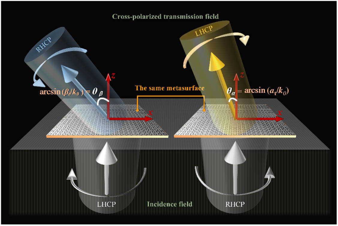
Figure 1.Schematic demonstration of a meta-deflector refracting transmitted wave with orthogonal polarization states into arbitrary and asymmetrical directions.
The basic physics of the independent manipulation of circular polarization can be considered as a combination of geometric and propagation phases. The combination of these two phases explains the synthesis of reverse symmetrical response (caused by geometric phase to LHCP and RHCP) and symmetrical response (caused by resonance phase to LHCP and RHCP), which will lead to totally different responses under LHCP and RHCP illuminations. For specific wavefront manipulations to be achieved, phase distributions on the metasurface need to be calculated before the construction of the metasurface. The Jones matrix, which describes the physical correlation between the transmitted wave and incident wave, can be used to derive the phase delays for the and polarizations required by the resonance phase and the rotating angles required by the geometric phase.
The proposed metasurface can be regarded as an inhomogeneous anisotropic surface, which can efficiently link the transmitted wave and incident wave by the Jones matrix . Now we suppose a monochromatic plane wave impinging onto the proposed metasurface along the axis, which can be described as any arbitrary polarization state . After passing through the metasurface, as desired, the transmitted output wave needs to have an opposite handedness , while acquiring a phase gradient along the axis, which introduces the off-axis refraction angle of the transmitted wave. This process can be described as where is the coordinate position of the unit cell along the axis. As for the orthogonal circularly polarized incident wave , the cross-polarized transmitted wave from the same metasurface could obtain the phase gradient (), and this process is described as It is important to note that the metasurface performs as a normal refraction meta-device when , which realizes a symmetrical refraction angle in only two orthogonal circular polarizations of the incident wave.
In order to perform the transformation established by Eqs. (1) and (2), the Jones matrix needs to be deduced, which exhibits independent effects on the two opposite circularly polarized incident waves. First, for the sake of simplicity, it is assumed that the two orthogonal polarization states of incident waves and are expressed in circular polarization states based on the linear polarization basis: By substituting Eq. (3) into Eqs. (1) and (2), the Jones matrix can be obtained as follows: This required Jones matrix pledges the feasibility of arbitrary refraction angles of transmitted waves with orthogonal circular polarizations. In order to establish the transformational relationship between the matrix and the construction of the unit cell, it can be obviously seen that the Jones matrix is unitary, which can be decomposed into its canonical form: where is the orthonormal matrix whose columns are the eigenvectors of , and is the diagonal matrix whose elements are the eigenvalues of . Under the linear polarization basis, it is observed from Eq. (5) that the eigenvectors of provide the orientation angle of the unit cell at the specific location , and the eigenvalues of offer the phase delays along the and directions and , which can be concluded as follows: It can be seen that the combined phase modulation can be achieved by artificially changing the geometric dimensions (for propagation phase response) and rotation angle (for geometrical phase response) of the unit cell at specific locations simultaneously on the metasurface. According to Eqs. (6)–(8), the construction parameters of the unit cell at any position along the axis can be confirmed by its phase delay , and rotation angle when phase gradients and are confirmed. In order to achieve independent control of LHCP and RHCP incidences with high efficiency, the response of the unit cell should fulfill: (1) the coverage of in both and ; (2) and can be independently tuned, and the difference between and is kept around ; and (3) the transmission coefficient can be kept at a high value. Once the distinct functionalities for orthogonal circular polarizations are fixed, the required phase interruption can be described by the Jones matrix.
3. DESIGN OF META-DEFLECTORS WITH DESIRED PHASE PROFILE
Next, we describe how to design unit cells satisfying Eqs. (6)–(8) simultaneously in order to establish a meta-deflector realizing polarization-controlled refraction. If we consider that the required phase delays along the and directions are varied with the position tuning in the direction, we need to find a series of unit cells whose structural size variation can affect the transmission phase both in the and directions directly. The working frequency is set as (). The unit cell is composed of two metallic layers separated by a dielectric substrate. Two concentric square ring-split apertures are made in both metallic layers with 180° rotation angle, as shown in Fig. 2(a). The symmetrical structure along the and axes ensures the suppression of the cross-polarized transmitted wave under impinging linear incidence. For the sake of description simplicity, one representative unit cell structure, whose side length of the outer slotted square split ring is 5.5 mm and that of the inner ring is 6.9 mm, is analyzed.

Figure 2.(a) Schematic of the proposed polarization-controlled refraction meta-deflector; inset shows the unit cell structure with the lattice period , width of slot , and gap length , and the thickness of the substrate with relative permittivity is . Simulated transmission (b) amplitude spectra and (c) phase spectra of the unit cell with and . Simulated transmission (d) amplitude and (e) phase delay along the direction, and transmission (f) amplitude and (g) phase delay along the direction as functions of two side lengths and changing from 3.5 mm to 7.0 mm with the other geometric parameters fixed. (h) Simulated phase delay and corresponding to the white dotted lined in (e) and (g), respectively.
Figures 2(b) and 2(c) show the different amplitudes and phases of transmission spectra of this representative unit cell. The amplitudes of both and are as high as 0.9 at 10 GHz, indicating that the transmitted wave is occupied mostly by a co-polarized wave, while the amplitudes of both and are near zero, meaning that there is almost no cross-polarized wave due to the symmetrical characteristics of the unit cell. Unit cells with multi-layered structures can be considered to further enhance the transmission coefficient in a wide frequency band. Meanwhile, the resonant frequency of unit cells with distinct geometric parameters and could be different from each other. The metasurface constructed by unit cells with variable dimensions contains a series of resonant frequencies, resulting in a broadband characteristic of the metasurface. On the other hand, ( for RHCP, for LHCP) proves that the implementation of a -phase difference can be achieved within a broad frequency band spanning from about 9 GHz to 11.5 GHz, which is in accordance with Eqs. (6) and (7). Hence, although different dimensions of unit cells resonate at different frequencies, the -phase difference between and polarizations is maintained over a wide frequency bandwidth, which guarantees the good broadband operation performances of polarization-independent refractions.
Figures 2(d)–2(g) report the simulation results of transmission amplitudes and and corresponding phase delays and along the and directions changing with varying and under the illumination of - and -polarized incident waves. It can be observed that there exists an area in the vicinity along the diagonal line of , where the amplitude and phase delay do not follow the same regularity as other areas, attributed to the overlap of inner and outer split-ring apertures. It is noted that the unit cells within this diagonal region, owning simply one single square ring aperture with width (), would produce different frequency responses from that of unit cells with double split apertures, which may not fully satisfy the primary condition of -phase difference between orthogonal linear polarizations. Thus, unit cells in this diagonal region are not selected to construct the metasurface structure. The white dotted lines in Figs. 2(e) and 2(g) describe the relationship between phase delay () and corresponding variable side length () with another geometric parameter () fixed, as extracted and shown in Fig. 2(h). It can be seen that the phase variation covers nearly the range of . The phase jumps shown in with [solid line in Fig. 2(h)] within the region of are caused by the overlap between the two square split-ring apertures, which also appear in with in the range of [dotted line in Fig. 2(h)]. Based on the results shown in Figs. 2(e) and 2(g), any unit cell with specific construction parameters to realize the required phase gradient along the and directions with -phase difference can be selected directly and conveniently.
Obviously, the realization of anomalous refraction based on a metasurface is in accordance with the generalized law of refraction [45], which can be described as where and are the angles of incidence and refraction, and are the refraction indices of the two media, is the wavelength, and represents the phase gradient along the axis in the proposed meta-deflector. Generally, there is a symmetrical characteristic in a conventional meta-deflector for the refracted wave with opposite handedness based solely on the geometric phase, as schematically depicted in Fig. 3(a). In this paper, in order to verify the feasibility of polarization-independent refraction based on the metasurface, two meta-deflectors are established.
Figure 3.Design of meta-deflectors for realizing polarized-independent refractions. (a) Schematic of the traditional deflector based on only geometric phase. Schematics of designed (b) meta-deflector 1 and (c) meta-deflector 2 for polarization-independent arbitrary refraction of the transmitted wave without symmetry for two opposite handednesses. Calculated phase delay , and rotation angle as functions of the coordinate of the unit cell along the direction for (d) meta-deflector 1 and (e) meta-deflector 2. Simulation results of transmitted phase delay , and difference for collected unit cells for (f) meta-deflector 1 and (g) meta-deflector 2.
For meta-deflector 1, two cross-polarized transmitted waves with opposite handedness deflect to the same side with regard to the propagation axis ( axis), and the phase gradients are set as and , where is the wave number (). By calculation, the transmitted refraction angle can be obtained as and when the meta-deflector is illuminated, respectively, by normally incident LHCP and RHCP waves, as expressed in Fig. 3(b). Here, the refraction angle is defined as the angle between transmitted wave and the axis, and the “+” and “−” labels stand for the transmitted wave deflecting towards the and directions, respectively. For meta-deflector 2, two orthogonal polarized waves deflect to two sides with regard to the axis, and the phase gradients are set as and . After calculation from Eq. (9), the refraction angles obtained under LHCP and RHCP incidences are and , as shown in Fig. 3(c).
On the basis of the determined phase gradients, the two meta-deflectors are constructed with 25 unit cells along the and directions, exhibiting a total dimension of 250 mm × 250 mm. The total thickness is about (), implying an ultra-thin planar structure compared to conventional optical applications. The phase delays and and rotation angle at specific positions along the direction are calculated and shown in Figs. 3(d) and 3(e), respectively. Appropriate unit cells are picked out based on the phase profiles shown in Figs. 2(d) and 2(f), which satisfy the requirement of phase delays for - and -polarized incident waves, as exhibited in the insets in Figs. 3(f) and 3(g). The detailed construction parameters of the collected unit cells for the two meta-deflectors are shown in Tables 1 and 2, respectively. The simulated results of transmission phase delays and for each collected unit cell for the two meta-deflectors are presented in Figs. 3(f) and 3(g), respectively, which are in accordance with the desired calculation in Figs. 3(d) and 3(e). The phase difference between and maintains and efficiently guarantees conversion of circular polarization.
| Unit Cell No. | 1 | 2 | 3 | 4 | 5 | 6 | 7 | 8 |
| l1 (mm) | 5.5 | 5.3 | 4.7 | 7.0 | 6.9 | 6.7 | 6.2 | 5.7 |
| l2 (mm) | 6.9 | 6.7 | 6.2 | 5.7 | 5.5 | 5.3 | 4.7 | 7.0 |
Table 1. Geometric Parameters of Selected Unit Cells for Meta-Deflector 1
| Unit Cell No. | 1 | 2 | 3 | 4 | 5 | 6 | 7 | 8 | 9 | 10 | 11 | 12 |
| l1 (mm) | 5.5 | 5.4 | 5.1 | 4.1 | 7.0 | 7.0 | 6.9 | 6.8 | 6.6 | 6.3 | 5.9 | 5.6 |
| l2 (mm) | 6.9 | 6.8 | 6.6 | 6.3 | 5.9 | 5.6 | 5.5 | 5.4 | 5.1 | 4.1 | 7.0 | 7.0 |
Table 2. Geometric Parameters of Selected Unit Cells for Meta-Deflector 2
4. SIMULATION AND EXPERIMENTAL RESULTS
In order to verify the performances of the designed meta-deflectors, full-wave simulations based on the finite difference time-domain (FDTD) technique are conducted at 10 GHz (). The schematic of the experimental setup is presented in Fig. 4(a), and the whole experimental measurements are conducted in a full anechoic chamber. A 2 GHz to 18 GHz dual polarized wideband horn antenna is adopted as the feeding source to launch the quasi-plane wave (LHCP and RHCP), which is placed at a distance away from the metasurface under test. The fabricated sample and receiver horn antenna are placed on a turntable to provide angular scanning. The electric field intensity distribution is recorded by a vector network analyzer (Agilent 8722 ES), which connects the source horn antenna and the receiver antenna simultaneously.
Figure 4.(a) Schematic of the experimental setup for far-field measurement. Photographs of fabricated (b) meta-deflector 1 and (c) meta-deflector 2 (top views); insets are enlarged illustrations of corresponding super cells. (d)–(k) Simulation and measurement results of transmitted cross-polarized waves emitted from meta-deflectors 1 and 2. For meta-deflector 1, (d) and (e) show simulated phase fronts of cross-polarized components in the transmitted field under RHCP and LHCP incidence. (f) and (g) show measured far-field distributions of cross-polarized components in the transmitted field under RHCP and LHCP incidence. For meta-deflector 2, (h) and (i) show simulated phase fronts of cross-polarized components in the transmitted field under RHCP and LHCP incidence. (j) and (k) show far-field distributions of cross-polarized components in the transmitted field under RHCP and LHCP incidence.
The metasurface samples are fabricated with the classical printed circuit board (PCB) technique, which is briefly described as follows. First, the polyfluortetraethylene dielectric substrates with double copper-cladding layers are prepared. Then the copper surface treatment is conducted for the dry film adhesion purpose, which is used as sensitive material to record printed circuit structures by exposure to ultraviolent (UV) rays. After the exposure process, the non-sensitizing dry film needs to be rinsed by a sodium carbonate photoresist developer. Furthermore, the exposed copper-covered areas are eliminated by a specific etching liquid and inner layer etching is performed. Finally, the process of black oxide for surface roughening and oxidization prevention is completed. Based on this PCB technique, the metasurface samples are fabricated and shown in Figs. 4(b) and 4(c), where the insets show the corresponding enlarged illustrations of a super-cell of meta-deflectors for a clearer view. It can be observed that the quality of fabricated samples is in accordance with our initial design requirements also at the level of meta-atom building.
For sample 1, Figs. 4(d) and 4(e) display the simulated phase fronts of cross-polarized components under the illumination of RHCP and LHCP incidence, respectively, indicating clearly that the transmitted wave is deflected from the axis by 14° and 30°, which are in good agreement with the theoretical calculations based on Eq. (9). The measured far-field intensity distributions of the cross-polarized components under incidence with different polarizations are presented in Figs. 4(f) and 4(g), as the function of frequency (9.0–11.5 GHz) and detection angles ( to 90°). It can be observed that the operation bandwidth of meta-deflector 1 is about 2.5 GHz with a relative bandwidth of 25%, where the LHCP and RHCP components in the transmitted field are obviously deflected into the required directions. Similarly, Figs. 4(h)–4(k) indicate corresponding simulated performances of meta-deflector 2. Both simulations of cross-polarized phase fronts and the measurements of normalized far-field intensity distributions are in accordance with the expected results shown in Fig. 3(c). It can be clearly observed that when meta-deflector 2 is illuminated by an RHCP plane wave, the cross-polarized transmitted wave deviates from the axis to the direction with 9°, whose phase front and far-field intensity profile are exhibited in Figs. 4(h) and 4(j). When illuminated by the LHCP incident plane wave, the phase front and far-field intensity profiles of the cross-polarized RHCP component all reveal the refraction characteristic of 41°, as depicted in Figs. 4(i) and 4(k).
Within this operating bandwidth, the lightest areas express the maximum value of far-field intensity distribution, and the refraction angle slightly changes against frequency, which can be understood as frequency dispersion, as expressed in Eq. (9). Furthermore, the dispersion problem could be solved by designing achromatic plasmonic components with compensation between structure and material dispersion [46], or by applying unit cells with true-time-delay characteristics.
In addition, the simulated and measured efficiencies of the meta-deflectors are evaluated and presented in Fig. 5. Here the transmission efficiency (TE) describes the transmittance characteristic of meta-deflectors, which can be calculated by the ratio of far-field intensity between the transmitted wave and incident wave. It can be seen in Figs. 5(a) and 5(b) that more than half of the incident energy can be transmitted by both meta-deflectors within the operation bandwidth, while the lost part of incident energy is caused mainly by inevitable reflections and substrate losses. On the other hand, conversion efficiency (CE) is defined as the ratio of the far-field intensity carried by the cross-polarized component to that carried by the whole transmitted wave, revealing the conversion ability of the meta-deflectors. As indicated in Figs. 5(c) and 5(d), the CE under LHCP incidence approaches 70%, and that under RHCP is about 80%.
Figure 5.Simulated and measured efficiencies of proposed meta-deflectors under opposite circularly polarized incidences. Transmission efficiencies of (a) meta-deflector 1 and (b) meta-deflector 2. Conversion efficiencies of (c) meta-deflector 1 and (d) meta-deflector 2. Black-thick lines represent LHCP incidence, while red-fine lines are for RHCP incidence; solid lines indicate measured efficiency, while dashed lines express simulated efficiency.
As mentioned above, -phase difference between - and -polarized responses is absolutely necessary for the cross-polarization conversion, and a high CE of each unit cell is ascertained by both high amplitude responses to and polarizations. However, it should be noted that within the frequency band of 9 GHz to 11.5 GHz, unit cells exhibit different amplitude responses to orthogonal linearly polarized incidences with the realization of a -phase difference, and thus a discrepancy between the amplitudes of opposite circularly polarized components occurs, resulting in different CEs of meta-deflectors for LHCP and RHCP incidences.
Furthermore, the meta-deflectors are constructed with unit cells having similar structural properties and different geometric dimensions, which may resonate at different frequency points and further lead to peaks in TEs. As for CEs, the primary influence factor is phase modulation, including phase interruption of each unit cell and constant phase interval between adjacent unit cells, which is fulfilled meticulously within the broadband width. Thus the CE curves are much smoother than TE curves. Nevertheless, the amplitude property has to be partly sacrificed for the phase conditions, leading to the fact that TEs cannot approach unity in the whole operation frequency band.
For the PCB technique used in fabrication in the microwave region, standard fabrication tolerance is 0.05 mm for copper-layer etching. Simulation results (not shown in the paper) have shown that the fabrication error has very little influence on the transmission coefficient and phase delay. The possible misalignment between front and back split-ring apertures that can be caused by fabrication error also has almost no influence on the response of the unit cell. Thus, the fabricated meta-deflectors can indeed achieve the preset polarization-independent refractions within the fabrication tolerance.
5. CONCLUSION
To summarize, a general scheme to design broadband ultra-thin metasurfaces for polarization-independent manipulation of an EM wave is presented in this paper. Two transmissive aperture-type meta-deflectors are proposed for arbitrary and asymmetrical refraction under orthogonal circularly polarized incidence in the microwave region. With the validation of theoretical calculations, full-wave simulations and experimental measurements have been performed for a proof of concept in the microwave region. The designed meta-deflectors have shown the ability to deflect transmitted waves into desired directions independently with high CE in a wide frequency range. Moreover, the deflected angles are independent of the incidence polarization. The design method proposed in this paper can be utilized to meet various requirements of microwave wireless communication systems, and stimulate the realizations of other performances and functionalities, as well as in other frequency regimes.
References
[1] M. Born, E. Wolf. Principles of Optics: Electromagnetic Theory of Propagation, Interference and Diffraction of Light(2013).
[2] M. Mutlu, A. E. Akosman, G. Kurt, M. Gokkavas, E. Ozbay. Experimental realization of a high-contrast grating based broadband quarter-wave plate. Opt. Express, 20, 27966-27973(2012).
[3] T. Sato, K. Shiraishi, K. Tsuchida, S. Kawakami. Laminated polarization splitter with a large split angle. Appl. Phys. Lett., 61, 2633-2634(1992).
[4] J. Sun, J. Li. Terahertz wave polarization splitter using full band-gap photonic crystals. Int. J. Infrared Millim. Waves, 36, 255-261(2015).
[5] C. C. Homes, G. L. Carr, R. P. S. M. Lobo, J. D. LaVeigne, D. B. Tanner. Silicon beam splitter for far-infrared and terahertz spectroscopy. Appl. Opt., 46, 7884-7888(2007).
[6] Y. Zhao, M. A. Belkin, A. Alu. Twisted optical metamaterials for planarized ultrathin broadband circular polarizers. Nat. Commun., 3, 870(2012).
[7] H. F. Ma, G. Z. Wang, W. X. Jiang, T. J. Cui. Independent control of differently-polarized waves using anisotropic gradient-index metamaterials. Sci. Rep., 4, 6337(2014).
[8] M. Khorasaninejad, K. B. Crozier. Silicon nanofin grating as a miniature chirality-distinguishing beam-splitter. Nat. Commun., 5, 5386(2014).
[9] H. Xu, G. Wang, T. Cai, J. Xiao, Y. Zhuang. Tunable Pancharatnam-Berry metasurface for dynamical and high-efficiency anomalous reflection. Opt. Express, 24, 27836-27848(2016).
[10] P. C. Wu, W. Y. Tsai, W. T. Chen, Y. W. Huang, T. Y. Chen, J. W. Chen, C. Y. Liao, C. H. Chu, G. Sun, D. P. Tsai. Versatile polarization generation with an aluminum plasmonic metasurface. Nano Lett., 17, 445-452(2016).
[11] Y. Xu, J. Xiao. Design of a compact and integrated TM-rotated/TE-through polarization beam splitter for silicon-based slot waveguides. Appl. Opt., 55, 611-618(2016).
[12] D. Sell, J. Yang, S. Doshay, J. A. Fan. Periodic dielectric metasurfaces with high-efficiency, multiwavelength functionalities. Adv. Opt. Mater., 5, 1700645(2017).
[13] X. Zhang, Z. Tian, W. Yue, J. Gu, S. Zhang, J. Han, W. Zhang. Broadband terahertz wave deflection based on C-shape complex metamaterials with phase discontinuities. Adv. Mater., 25, 4567-4572(2013).
[14] T. Cai, G. M. Wang, X. F. Zhang, J. G. Liang, Y. Q. Zhuang, D. Liu, H. X. Xu. Ultra-thin polarization beam splitter using 2-D transmissive phase gradient metasurface. IEEE Trans. Antennas Propag., 63, 5629-5636(2015).
[15] S. Boroviks, R. A. Deshpande, N. A. Mortensen, S. I. Bozhevolnyi. Multifunctional metamirror: polarization splitting and focusing. ACS Photon., 5, 1648-1653(2017).
[16] H. Xu, S. Tang, C. Sun, L. Li, H. Liu, X. Yang, F. Yuan, Y. Sun. High-efficiency broadband polarization-independent superscatterer using conformal metasurfaces. Photon. Res., 6, 782-788(2018).
[17] B. Ratni, A. de Lustrac, G.-P. Piau, S. N. Burokur. A reconfigurable meta-mirror for wavefronts control: applications to microwave antennas. Opt. Express, 26, 2613-2624(2018).
[18] Y. Xu, C. Gu, B. Hou, Y. Lai, J. Li, H. Chen. Broadband asymmetric waveguiding of light without polarization limitations. Nat. Commun., 4, 2561(2013).
[19] J. Wang, X. Wang, H. Shao, Z. Hu, G. Zheng, F. Zhang. Peak modulation in multicavity-coupled graphene-based waveguide system. Nanoscale Res. Lett., 12, 9(2017).
[20] A. Nemati, Q. Wang, M. Hong, J. Teng. Tunable and reconfigurable metasurfaces and metadevices. Opto-Electron. Adv., 1, 180009(2018).
[21] D. Wang, L. Zhang, Y. Gu, M. Q. Mehmood, Y. Gong, A. Srivastava, L. Jian, T. Venkatesan, C. Qiu, M. Hong. Switchable ultrathin quarter-wave plate in terahertz using active phase-change metasurface. Sci. Rep., 5, 15020(2015).
[22] X. Chen, M. Chen, M. Q. Mehmood, D. Wen, F. Yue, C. W. Qiu, S. Zhang. Longitudinal multifoci metalens for circularly polarized light. Adv. Opt. Mater., 3, 1201-1206(2015).
[23] D. Lin, A. L. Holsteen, E. Maguid, G. Wetzstein, P. G. Kik, E. Hasman, M. L. Brongersma. Photonic multitasking interleaved Si nanoantenna phased array. Nano Lett., 16, 7671-7676(2016).
[24] H. Yang, G. Li, G. Cao, Z. Zhao, F. Yu, X. Chen, W. Lu. Polarization-independent metalens constructed of antennas without rotational invariance. Opt. Lett., 42, 3996-3999(2017).
[25] E. Hasman, V. Kleiner, G. Biener, A. Niv. Polarization dependent focusing lens by use of quantized Pancharatnam-Berry phase diffractive optics. Appl. Phys. Lett., 82, 328-330(2003).
[26] Z. Zhang, D. Wen, C. Zhang, M. Chen, W. Wang, S. Chen, X. Chen. Multifunctional light sword metasurface lens. ACS Photon., 5, 1794-1799(2018).
[27] X. Ding, F. Monticone, K. Zhang, L. Zhang, D. Gao, S. N. Burokur, A. Lustrac, Q. Wu, C. Qiu, A. Alù. Ultrathin Pancharatnam-Berry metasurface with maximal cross-polarization efficiency. Adv. Mater., 27, 1195-1200(2015).
[28] M. L. N. Chen, L. J. Jiang, W. E. I. Sha. Ultrathin complementary metasurface for orbital angular momentum generation at microwave frequencies. IEEE Trans. Antennas Propag., 65, 396-400(2017).
[29] J. He, X. Wang, D. Hu, J. Ye, S. Feng, Q. Kan, Y. Zhang. Generation and evolution of the terahertz vortex beam. Opt. Express, 21, 20230-20239(2013).
[30] W. Luo, S. Sun, H.-X. Xu, Q. He, L. Zhou. Transmissive ultrathin Pancharatnam-Berry metasurfaces with nearly 100% efficiency. Phys. Rev. Appl., 7, 044033(2017).
[31] H. Xu, H. Liu, X. Ling, Y. Sun, F. Yuan. Broadband vortex beam generation using multimode Pancharatnam-Berry metasurface. IEEE Trans. Antennas Propag., 65, 7378-7382(2017).
[32] J. Zeng, L. Li, X. Yang, J. Gao. Generating and separating twisted light by gradient-rotation split-ring antenna metasurfaces. Nano Lett., 16, 3101-3108(2016).
[33] K. Zhang, Y. Yuan, D. Zhang, X. Ding, B. Ratni, S. N. Burokur, M. Lu, K. Tang, Q. Wu. Phase-engineered metalenses to generate converging and non-diffractive vortex beam carrying orbital angular momentum in microwave region. Opt. Express, 26, 1351-1360(2018).
[34] A. Arbabi, Y. Horie, M. Bagheri, A. Faraon. Dielectric metasurfaces for complete control of phase and polarization with subwavelength spatial resolution and high transmission. Nat. Nanotechnol., 10, 937-943(2015).
[35] S. M. Kamali, E. Arbabi, A. Arbabi, Y. Horie, M. Faraji-Dana, A. Faraon. Angle-multiplexed metasurfaces: encoding independent wavefronts in a single metasurface under different illumination angles. Phys. Rev. X, 7, 041056(2017).
[36] M. Khorasaninejad, A. Ambrosio, P. Kanhaiya, F. Capasso. Broadband and chiral binary dielectric meta-holograms. Sci. Adv., 2, e1501258(2016).
[37] D. Wen, F. Yue, G. Li, G. Zheng, K. Chan, S. Chen, M. Chen, K. F. Li, P. W. H. Wong, K. W. Cheah, E. Y. B. Pun, S. Zhang, X. Chen. Helicity multiplexed broadband metasurface holograms. Nat. Commun., 6, 8241(2015).
[38] Z. Wang, X. Ding, K. Zhang, B. Ratni, S. N. Burokur, X. Gu, Q. Wu. Huygens metasurface holograms with the modulation of focal energy distribution. Adv. Opt. Mater., 6, 1800121(2018).
[39] J. P. B. Mueller, N. A. Rubin, R. C. Devlin, B. Groever, F. Capasso. Metasurface polarization optics: independent phase control of arbitrary orthogonal states of polarization. Phys. Rev. Lett., 118, 113901(2017).
[40] B. Wang, F. Dong, H. Feng, D. Yang, Z. Song, L. Xu, W. Chu, Q. Gong, Y. Li. Rochon-prism-like planar circularly polarized beam splitters based on dielectric metasurfaces. ACS Photon., 5, 1660-1664(2017).
[41] R. C. Devlin, A. Ambrosio, N. A. Rubin, J. P. B. Mueller, F. Capasso. Arbitrary spin-to-orbital angular momentum conversion of light. Science, 358, 896-901(2017).
[42] S. Fu, T. Wang, Z. Zhang, Y. Zhai, C. Gao. Selective acquisition of multiple states on hybrid Poincare sphere. Appl. Phys. Lett., 110, 191102(2017).
[43] T. Cai, S. Tang, G. Wang, H. Xu, S. Sun, Q. He, L. Zhou. High-performance bifunctional metasurfaces in transmission and reflection geometries. Adv. Opt. Mater., 5, 1600506(2017).
[44] H. Zhang, X. Zhang, Q. Xu, C. Tian, Q. Wang, Y. Xu, Y. Li, J. Gu, Z. Tian, C. Ouyang, X. Zhang, C. Hu, J. Han, W. Zhang. High-efficiency dielectric metasurfaces for polarization-dependent terahertz wavefront manipulation. Adv. Opt. Mater., 6, 1700773(2018).
[45] N. Yu, P. Genevet, M. A. Kats, F. Aieta, J. P. Tetienne, F. Capasso, Z. Gaburro. Light propagation with phase discontinuities: generalized laws of reflection and refraction. Science, 334, 333-337(2011).
[46] Y. Li, X. Li, M. Pu, Z. Zhao, X. Ma, Y. Wang, X. Luo. Achromatic flat optical components via compensation between structure and material dispersions. Sci. Rep., 6, 19885(2016).


