• Chinese Optics Letters
  • Vol. 13, Issue 2, 021101 (2015)
Zichen Cao, Qing Cao*, Yajun Ge, Rongfei Hu, and Minning Zhu
Author Affiliations
  • Department of Physics, Shanghai University, Shanghai 200444, China
  • show less
    DOI: 10.3788/COL201513.021101 Cite this Article Set citation alerts
    Zichen Cao, Qing Cao, Yajun Ge, Rongfei Hu, Minning Zhu. Trapezoidal phase mask coronagraph[J]. Chinese Optics Letters, 2015, 13(2): 021101 Copy Citation Text show less
    Setup of the coronagraph system. System is composed of three imaging lenses (L1, L2, and L3) with the same focal length f, an AS, a trapezoidal phase mask, a LS, and a detecting receiver like a CCD camera. Distance between LS and L2 has been set to be 2f to compensate for an extra phase factor caused by pressing the AS upon L1.
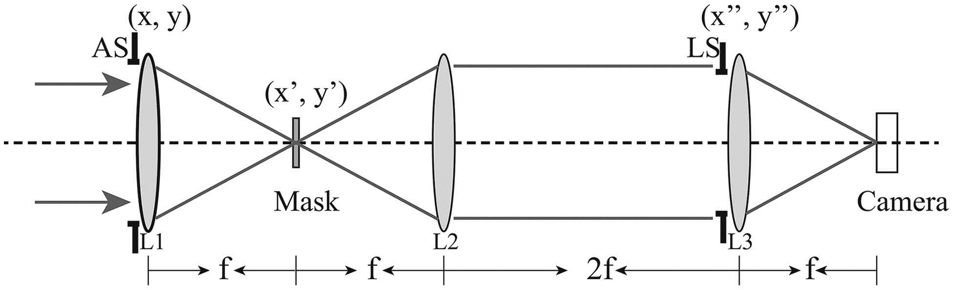
    Fig. 1. Setup of the coronagraph system. System is composed of three imaging lenses (L1, L2, and L3) with the same focal length f, an AS, a trapezoidal phase mask, a LS, and a detecting receiver like a CCD camera. Distance between LS and L2 has been set to be 2f to compensate for an extra phase factor caused by pressing the AS upon L1.
    (a) 3D plot of azimuthal phase distribution of the mask; (b) corresponding phase distribution in the azimuthal direction for the designed central wavelength λ0. TPM is double-periodic in the azimuthal direction; each period contains two reversed full trapezoids and one flat region.
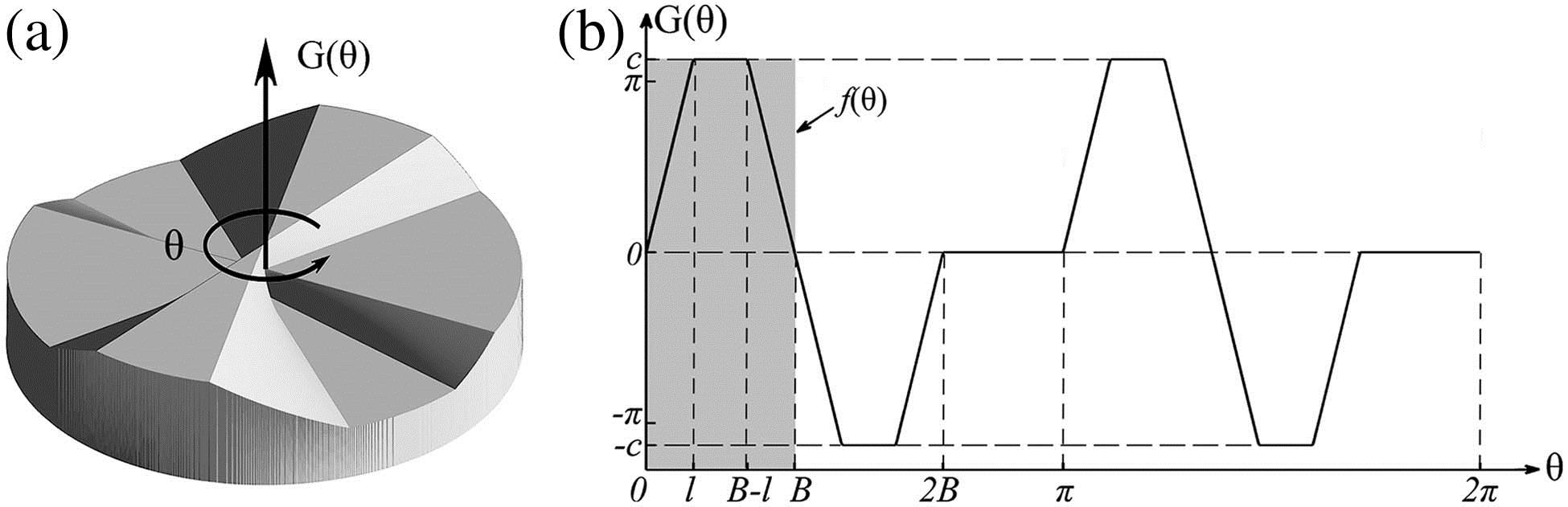
    Fig. 2. (a) 3D plot of azimuthal phase distribution of the mask; (b) corresponding phase distribution in the azimuthal direction for the designed central wavelength λ0. TPM is double-periodic in the azimuthal direction; each period contains two reversed full trapezoids and one flat region.
    Normalized intensity distribution at the LS plane after being modulated by different phase masks; (a) SLPM (B=6π/24); (b) TPM when B=7π/24; (c) TPM when B=8π/24; (d) TPM when B=9π/24. Radius of the central dark circular is 1. Color represents the relative light intensity.
    Fig. 3. Normalized intensity distribution at the LS plane after being modulated by different phase masks; (a) SLPM (B=6π/24); (b) TPM when B=7π/24; (c) TPM when B=8π/24; (d) TPM when B=9π/24. Radius of the central dark circular is 1. Color represents the relative light intensity.
    Comparison between the peak throughput of SLPM, FQPM (dashed line), and TPM with different values of B (solid line, B=7π/24; dotted line, B=8π/24; dash-dot line, B=9π/24).
    Fig. 4. Comparison between the peak throughput of SLPM, FQPM (dashed line), and TPM with different values of B (solid line, B=7π/24; dotted line, B=8π/24; dash-dot line, B=9π/24).
    Comparison between the planet throughput variation of the TPM (B=7π/24) and the SLPM (equivalent to the FQPM) in the angular direction ranging from 0 to π (one period). Two angular distances (solid line, λ/d=1.0; dashed line, λ/d=2.0) have been considered.
    Fig. 5. Comparison between the planet throughput variation of the TPM (B=7π/24) and the SLPM (equivalent to the FQPM) in the angular direction ranging from 0 to π (one period). Two angular distances (solid line, λ/d=1.0; dashed line, λ/d=2.0) have been considered.
    Comparison among the value |C0(λ)|2 of the TPM with B=7π/24 (grey dot curve), the FQPM (black dash-dot curve), and the SLPM (solid curve) for different λ0/λ. Inset, detailed view of the TPM and SLPM.
    Fig. 6. Comparison among the value |C0(λ)|2 of the TPM with B=7π/24 (grey dot curve), the FQPM (black dash-dot curve), and the SLPM (solid curve) for different λ0/λ. Inset, detailed view of the TPM and SLPM.
    Zichen Cao, Qing Cao, Yajun Ge, Rongfei Hu, Minning Zhu. Trapezoidal phase mask coronagraph[J]. Chinese Optics Letters, 2015, 13(2): 021101
    Download Citation