An angular trapezoidal phase mask used for a wideband coronagraph is proposed. The azimuthal phase of the mask is double-periodic and has both trapezoidal and constant parts in each period. This kind of continuous phase distribution can be employed to avoid the abrupt phase variation of the 6-level phase distribution we proposed previously. Numerical calculations show that this more practical phase mask can still keep its superior performance in terms of starlight elimination, small inner working angle, and good achromatism. It is of great importance that there is no singularity in this kind of mask except for a singularity at the center. This mask design is close to real manufacturing conditions, and the process technology is superior.
Direct imaging of an exoplanet is very hard to obtain, because the host star of the target planet is usually times brighter in the visible region ( times in the infrared region) than the Earth-like exoplanet. Coronagraphs can largely eliminate the glaring light of the host star and make it possible to discover and analyze its orbiting planets. In recent years, various coronagraph designs have been proposed and widely discussed[1]; for example, the amplitude mask coronagraph[2], the pupil apodized coronagraph[3], and the phase mask coronagraph[4–21]. Since phase mask coronagraphs have advantages such as small inner working angle (IWA), high throughput, and direct imaging, some of them have been mounted on the best telescopes in the world[5,6]. The nulling stellar coronagraph using a circular π-shifting mask was first proposed and discussed[7], the four-quadrant phase mask (FQPM) coronagraph employs a four-quadrant binary phase mask[5,8], and the optical vortex coronagraph uses an optical vortex mask of even topological charge[9–14]. An eight-octant phase mask (EOPM) coronagraph which provides a phase difference between the adjacent eight octants at the focal plane has also been studied[15]. Those phase masks used in coronagraphs are somewhat related to the topic of beam shaping, especially the generation, propagation, and transform of light beams in cylindrical coordinates[22–25].
As the phase mask is sensitive to the wavelength of incident light, the problem of chromatism should be taken into consideration. To increase the bandwidth of a coronagraph different technologies are employed (such as subwavelength gratings, liquid crystal polymers, photonic crystals[15–17], and multi-stage devices[18,19]). Recently, we have proposed the sinusoidal phase mask coronagraph (SPM)[20] and the six-level phase mask coronagraph (SLPM)[21]; both designs could increase the bandwidth due to the inherent characteristic of the mask. However, the abrupt phase variation of an ideal SLPM is difficult to realize in actual fabrications. In order to avoid such abrupt phase variation, in this Letter we propose a trapezoidal phase mask coronagraph (TPM), which is also a more general form of the SLPM.
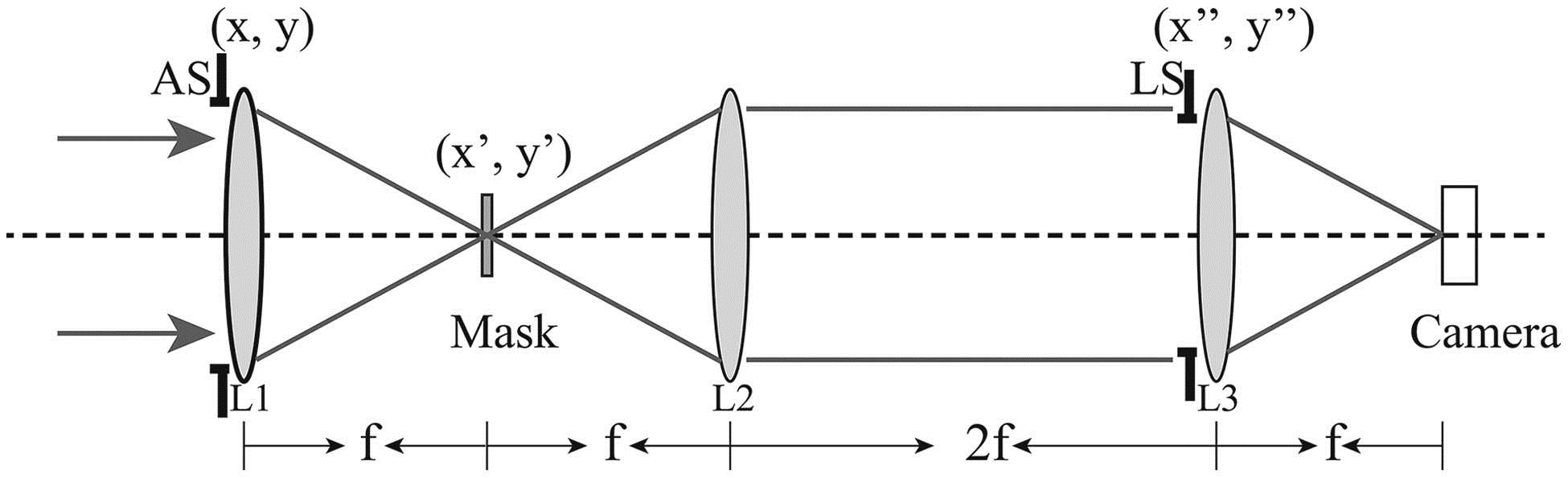
The setup of the coronagraph system is shown in Fig. 1. As we can see, the phase mask is put at the focal plane , and the system reimages the entrance pupil at the Lyot stop (LS) plane. According to Refs. [20,21], the total complex amplitude distribution at the LS plane can be derived as which have adopted notation similar to Ref. [20], where , the initial plane wave with an amplitude is the incident starlight from far away traveling along the optical axis in our work, is the central wavelength of a wideband light, is the focal length of the imaging lenses, is the radius of the aperture stop (AS), and the AS function [defined as 1 for , and 0, otherwise, where ], is the azimuthal coordinate of the transverse plane , , is the th order Hankel transform[26], , and , as the weight factor, regulates the percentage of the starlight intensity of different order in the conjugate pupil plane,
Sign up for Chinese Optics Letters TOC. Get the latest issue of Chinese Optics Letters delivered right to you!Sign up now
Figure 1.Setup of the coronagraph system. System is composed of three imaging lenses (L1, L2, and L3) with the same focal length , an AS, a trapezoidal phase mask, a LS, and a detecting receiver like a CCD camera. Distance between LS and L2 has been set to be to compensate for an extra phase factor caused by pressing the AS upon L1.
Accordingly, , is an arbitrary integer, is the transition function of the phase mask, and is the azimuthal coordinate of the plane .
When taking the bandwidth of the incident starlight into account, we should express the transition function as , where is a double-periodic phase function in the azimuthal direction, and . The expression of for the designated central wavelength in one period is given by Ref. [21], which is Furthermore, in order to effectively eliminate the on-axis starlight (with central wavelength ), and meanwhile to obtain better achromatism at the plane , two additional equations should be satisfied in the end[20,21], which are
Equation (4a) implies that, for the central wavelength, the energy passing through the LS plane should be zero for the design in theory, while Eq. (4b) makes the variation of smooth at the vicinity of . Now in our TPM, the specific function , depicted in Fig. 2(b) within the grey-shaded area, has been defined as
Figure 2.(a) 3D plot of azimuthal phase distribution of the mask; (b) corresponding phase distribution in the azimuthal direction for the designed central wavelength . TPM is double-periodic in the azimuthal direction; each period contains two reversed full trapezoids and one flat region.
Figure 2(b) shows the whole phase profile of the TPM, which is composed of and constant parts section by section. The 3D plot of the azimuthal phase distribution of the mask in Fig. 2(a) makes it easier to understand.
Once we determined the phase function , by substituting Eqs. (2), (3) and (5) into Eq. (4), we can obtain the relations among , , and , as These parameters should also meet the conditions and , to ensure that each period in Fig. 2(b) always contains two reversed full trapezoids and one flat region.
Researchers may find that when equals zero, of the TPM is equivalent to that of the SLPM. However, when , the function varies continuously in the azimuthal direction without abrupt phase variations (unlike such masks as FQPM, EOPM, and SLPM). This trapezoidal phase design avoids the impact brought by steep phase shifts and is closer to the real result of the manufacturing process[10].
In order to evaluate the performance of the TPM, we choose three specific values for (, , and ) and calculate the three corresponding values for with four-decimal precision (3.2623, 3.4270, and 3.6908). Note that should range from to [derived from the Eqs. (3) and (6)]; if , the TPM turns into the SLPM.
Figure 3 shows the monochromatic intensity distribution of the incident starlight (central wavelength ) in front of the LS plane, and each TPM is with a different value of ; in Fig. 3(b), in Fig. 3(c), and in Fig. 3(d). The result of the SLPM () in Fig. 3(a) is shown as a comparison. A fast Fourier-transform (FFT) algorithm applied on arrays with has been applied in the simulation without taking the wave-front error and phase error into consideration. The obtained images each have a dark blue circular area in the center (theoretically, the radius of the area equals ), within which the starlight has been totally eliminated, theoretically. For monochromatic incident light with the designed central wavelength, the TPM is as good as the SLPM in starlight elimination. Under ideal conditions, the point spread function (PSF) of the TPM inside the LS equals zero; it is the same as that of the SPM and the SLPM. To totally eliminate the diffracted light outside, is needed, where is the radius of the LS[20]. Yet in practical conditions, little residual of will still exist inside the LS and is usually uniformly distributed, and the PSF at the camera is in accordance with a Jinc function.
Figure 3.Normalized intensity distribution at the LS plane after being modulated by different phase masks; (a) SLPM (); (b) TPM when ; (c) TPM when ; (d) TPM when . Radius of the central dark circular is 1. Color represents the relative light intensity.
The phase mask at focal plane not only affects the starlight throughput, but also the off-axis light from the planet. The IWA defined as the angular distance at which the throughput of the planet in orbit is half of the maximal throughput, is one of the most important criteria of the coronagraph design[1]. In the case of the TPM, as the general form of the SLPM, the IWA is not abruptly influenced. Figure 4 shows the peak throughput variations of different masks with respect to , the SLPM (equivalent to the FQPM), and the TPM with different values of ; the method calculating the peak throughput is similar to that of Ref. [20]. The transforming range includes over 70 sidelobes at the frequency domain, and we also assume that the planet locates at the angle bisector of one zero-region of the mask. As shown in Fig. 4, the peak throughput gradually decreases with the increase of (from to ). When , the IWA is around , and the single flat area of the TPM is already larger than .
Figure 4.Comparison between the peak throughput of SLPM, FQPM (dashed line), and TPM with different values of (solid line, ; dotted line, ; dash-dot line, ).
As the TPM is circularly asymmetric, the off-axis throughput (from the planet) differs with respect to the places on the mask through which the planet light passes. Researchers can rotate the mask in order to get a high throughput for the same planet. Figure 5 shows the throughput variation of the planet light in an angular direction ranging from 0 to (one period), the TPM () being comparable to that of the SLPM (and also the FQPM). For the TPM, the throughput reaches its maximum when the planet light is projected on the angle bisector of the zero region, which is . For the SLPM (and also the FQPM), the throughput reaches its maximum twice in one period, one at the angle bisector of its zero region, and the other at that very region of the abrupt phase variation. However, by comparing both results of the SLPM and the TPM, one may notice that at the region of abrupt phase variation, there is merely a poor tolerance of a stable high throughput, because the throughput of the TPM at this region drops more rapidly than that within the zero region. The throughputs of the TPM and the SLPM (and also FQPM) within the zero region (near the angle ) both are above 0.5 (for both angular distances and ).
Figure 5.Comparison between the planet throughput variation of the TPM () and the SLPM (equivalent to the FQPM) in the angular direction ranging from 0 to (one period). Two angular distances (solid line, ; dashed line, ) have been considered.
The property of achromatism of the TPM and SLPM originates from the additional constraint from Eq. (6). The achromatic performance can be expressed by the variation of with respect to different wavelengths, because is only related to the integrated energy inside the LS. It can be proven that of the FQPM, the SLPM[20,21], and the TPM [derived from Eqs. (2), (3), and (5)] can be respectively written as
Note that when , of the TPM becomes the same as that of the SLPM.
Figure 6 shows variations of the TPM in comparison with the SLPM, and the FQPM with respect to the value of . The wideband performance of the TPM is a little bit better than that of the SLPM, but both are much more effective than the single FQPM (monochromatic FQPM). When the value of lies between 0.9 and 1.13, of the TPM and SLPM are both less than . As the denominator, a longer central wavelength makes the achromatic performance even better.
Figure 6.Comparison among the value of the TPM with (grey dot curve), the FQPM (black dash-dot curve), and the SLPM (solid curve) for different . Inset, detailed view of the TPM and SLPM.
In conclusion, as the general pattern of the SLPM, the trapezoid phase mask coronagraph still keeps good starlight elimination and a small IWA around . Although the simulation is carried out under ideal conditions, the TPM itself is designed with consideration of mask manufacturing in practical situations, which increases the degree of freedom in the mask design and enables more accurate mask designs as well. For example, a mask using can be manufactured by an electron-beam process or direct laser writing, and masks using liquid crystals[27] are also reported. The TPM maintains a broad bandwidth due to its similarity to the SLPM. Moreover, the effect of the aberration coming from the coronagraph system of the SLPM is similar to that of the FQPM since the SLPM is in accordance with the FQPM. The capabilities of the coronagraph to cope with an obscured pupil, low-order aberrations, and numerical noise and errors (from optical devices of the FQPM or other masks) are tested with simulations and in lab experiments[8,14,15]. The performance of the mask in this work is given under ideal conditions.