Key Laboratory of Luminescence and Optical Information, Ministry of Education, School of Physical Science and Engineering, Beijing Jiaotong University, Beijing 100044, China
Yu Li, Shuaibing Wang, Jie Chen, Ouyang Lin, Zhe Yin, Chunhe Yang, Aiwei Tang. From kesterite 2D nanosheets to wurtzite 1D nanorods: controllable synthesis of Cu−Zn−Sn−S and their application in electrocatalytic hydrogen evolution[J]. Journal of Semiconductors, 2023, 44(12): 122701
Copy Citation Text
As typical quarternary copper-based chalcogenides, Cu–Zn–Sn–S nanocrystals (CZTS NCs) have emerged as a new-fashioned electrocatalyst in hydrogen evolution reactions (HERs). Oleylamine (OM), a reducing surfactant and solvent, plays a significant role in the assisting synthesis of CZTS NCs due to the ligand effect. Herein, we adopted a facile one-pot colloidal method for achieving the structure evolution of CZTS NCs from 2D nanosheets to 1D nanorods assisted through the continuous addition of OM. During the process, the mechanism of OM-induced morphology evolution was further discussed. When merely adding pure 1-dodecanethiol (DDT) as the solvent, the CZTS nanosheets were obtained. As OM was gradually added to the reaction, the CZTS NCs began to grow along the sides of the nanosheets and gradually shrink at the top, followed by the formation of stable nanorods. In acidic electrolytic conditions, the CZTS NCs with 1.0 OM addition display the optimal HER activity with a low overpotential of 561 mV at 10 mA/cm2 and a small Tafel slope of 157.6 mV/dec compared with other CZTS samples. The enhancement of HER activity could be attributed to the contribution of the synergistic effect of the diverse crystal facets to the reaction.
The rapid consumption of traditional fossil energy has made it difficult to meet sustainable economic and environmental development, which accelerates the exploration and utilization of renewable energy sources[1−3]. Hydrogen energy (H2), one of the most promising alternatives, has aroused widespread attention due to its high energy density and cleaning products[4, 5]. Electrocatalytic water splitting into hydrogen is considered a high-efficient renewable energy production route. However, the thermodynamic barrier and slow kinetics severely hinder the efficiency of hydrogen evolution reaction (HERs), and developing efficient electrocatalysts are needed to overcome the above problems[6]. Among all the existing electrocatalysts, the most common efficient electrocatalysts are mainly Pt-based noble metal nanomaterials. Unfortunately, their commercial application is severely impeded by their scarcity and high cost[7]. Consequently, developing low-cost, abundant, and high-efficient electrocatalysts has become the current research focus.
Quaternary copper-based chalcogenides, especially for Cu−Zn−Sn−S nanocrystals (CZTS NCs), have been considered as promising nanomaterials for photocatalysis and electrocatalysis owing to their abundant elements, tunable structures, and low toxicity[8−12]. Recently, researchers had devoted greateffort to developing CZTS nanomaterials with various shapes, sizes, and crystalline phases for HERs. Current reports about their synthesized methods involve solvothermal[13], colloidal synthesis[14, 15] and sonochemical methods[11, 16−20], etc. However, most of them require high-temperature and high-pressure conditions, and the obtained nanocrystals perform polydispersed and multi-sized[11]. To obtain high-quality and well-monodispersed nanocrystals, surface ligands are required in the colloidal method. As we all know, during the growth phase, selective adsorption of ligands to different crystal faces could contribute to the formation of nanocrystals with different dimensions and morphologies[21, 22]. Particularly, oleylamine (OM) is a typical reducing surfactant and solvent, which plays a significant role in the controllable synthesis of nanocrystals[23, 24]. However, the modulation mechanism is needed to be deeply explored. Consequently, it is indispensable to design reasonable experiment systems to elucidate the critical role of OM in modulating shapes, sizes, and crystal forms of CZTS nanocrystals.
In this work, we reported the controllable synthesis of a variety of CZTS NCs using OM as the surfactant and demonstrated the potential in electrocatalytic HER. Through changing the additional amount of OM, the evolution of morphologies and crystal phases of CZTS NCs gradually occurred. The evolution mechanism of the morphologies was further emphasized. It turns out that OM could control the growth direction of CZTS NCs from nanosheets to nanorods due to the selective adsorption of OM to different crystal facets. Meanwhile, the process is also accompanied by the transformation of the crystal phases from kesterite to wurtzite. The electrochemical properties were measured to investigate the electrocatalytic hydrogen evolution activity of these CZTS NCs. The results demonstrated that the CZTS-1.0 possessed the minimum thermodynamic energy barrier and the fastest reaction kinetics compared with other CZTS samples.
Experimental methods
OM-assisted synthesis of CZTS nanocrystals
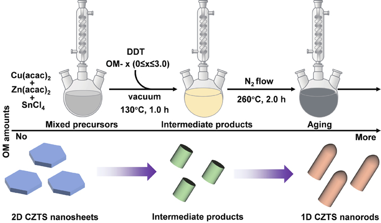
A set of quaternary CZTS NCs were typically synthesized via a one-pot colloidal method as shown in Fig. 1. First, for the synthesis of CZTS nanosheets, three precursor metallic salts including Cu(acac)2 (1.0 mmol), Zn(acac)2 (0.5 mmol) and SnCl4 (0.5 mmol, 58.5 μL) were dispersed to 10 mL 1-dodecanethiol (DDT) without other solvents in the three-neck flask. Then, the flask slowly was heated to 130 °C and kept at 130 °C for 60 min to eliminate water and dissolved oxygen in vacuo with vigorous magnetic stirring. After the formation of a homogeneous solution, the reaction temperature was further improved to 260 °C and kept at 260 °C with N2 protection for 120 min. Then, the reaction solution was naturally cooled down to room temperature. The crude solution was isolated by adding the mixed solvent of chloroform and ethanol, and centrifugated to remove unreacted precursors. The as-obtained precipitates were then washed by repeating the process five times. Finally, the resultant samples were dried under a vacuum or dispersed in a chloroform solvent for further characterization. Then, introducing the ligand solvent OM to the above reaction system and controlling the adding amount (0.5, 1.0, 1.5, 2.0, and 3.0 mL) was carried out and a series of CZTS NCs with a structure evolution was synthesized.
Figure 1.(Color online) Schematic illustration of the OM-assisted synthesis process and the structural evolution of CZTS nanocrystals.
Before the measurement of electrocatalytic performance, all CZTS nanocrystals were first transferred from the non-polar solvents into the aqueous solution by a pre-established ligand-exchange strategy[25]. Typically, the synthesized CZTS NCs (50 mg) with hydrophobic ligands (DDT and OM) were dissolved in 5 mL chloroform (solution Ⅰ). 0.5 g KOH was added to 20 mL methanol with 1.0 mL MPA (solution Ⅱ). Then, the solution Ⅰwas swiftly added to solution Ⅱ. The mixing solution was stirred at room temperature for 8 h. The NCs were collected by centrifugation and washed with water and methanol twice until the rest ligand was removed. The final products were dried under a vacuum at 60 °C overnight. The CZTS samples with different OM-adding amounts are marked as CZTS-n (0 ≤ n ≤ 3 mL).
Electrochemical measurements
All electrocatalytic measurements of as-synthesized CZTS NCs were performed by using three-electrode equipment from the electrochemical workstation at room temperature. The prepared samples supported on a glassy carbon electrode (GCE, 3 mm in dia.) were adopted as working electrodes, and a high-purity carbon rod (d = 6 mm) and Ag/AgCl electrodes were used for counter electrodes and reference electrodes, respectively. Furthermore, 0.5 M H2SO4 aqueous solution was used as the electrolyte. The working electrode was fabricated using 5.0 mg of the catalyst dispersed into a mixture of the solvent containing 100 : 1 of the isopropanol/Nafion (5wt%) solution and then the mixture was sonicated for 30 min to form a homogeneous ink. 20 μL (0.82 mg) of the catalytic ink was loaded onto the GCE and dried naturally at room temperature. The polarization curves (LSV) were obtained at a scan rate of 5 mV/s after CV activation at the non-Faraday region (2 mV/s). The conversion formula of the potentials is E (RHE) = E (Ag/AgCl) + 0.244 V.
Characterization
Transmission electron microscopy (TEM) images were recorded on a JEM-1400 transmission electron microscope operating at an accelerating voltage of 100 kV. The X-ray diffraction (XRD) patterns were obtained with a Bruker D8 Advance diffractometer equipped with a Cu Kα radiation source (λ = 1.54056 Å). The 2θ range changed from 20° to 80° at a scanning rate of 10°/min. The electrocatalytic performances of the as-synthesized samples were tested in a three-electrode system using an electrochemical workstation (CHI 660E, Shanghai).
Results and discussion
OM-assisted synthesis of CZTS nanocrystals
Adding surfactants to colloidal synthesis could control the crystal nucleation and growth process thanks to their coordination effect with nanocrystals[21]. OM, as a typical reducing ligand, has been widely used to modulate the morphology and crystal phase of nanocrystals[23, 24]. Thus, it is essential to explore the significant role of OM in the synthesis of CZTS NCs, which is helpful to understand the mechanism of structure modulation and transformation. In this work, a facile one-pot colloidal method was adopted to synthesize a series of quaternary CZTS NCs assisted by adding OM. According to the different amounts added, these samples could be symbolled as CZTS-n (0 ≤ n ≤ 3 mL). In Fig. 1, we started with the preparation of CZTS NCs without OM adding (CZTS-0) through heating metal precursors, including Cu(acac)2, Zn(acac)2 and SnCl4 in 1-dodecanethiol (DDT) at 260 °C for 120 min, where DDT was chosen as the sulfur source, reaction medium and capping ligand[26]. As shown in Fig. 2(a), the XRD pattern indicated that the as-obtained CZTS-0 possesses two coexisting crystal phases of kesterite and wurtzite, and the major diffraction peaks can be indexed to kesterite-dominant CZTS (JCPDS 26-0575). Furthermore, the TEM image of kesterite CZTS NCs is shown in Fig. 2(b). It could be seen that they show two-dimensional (2D) hexagonal nanosheets with a thin layer structure, and have good monodispersity and uniform size. The average diameter of the hexagonal nanosheets is 31.8 ± 6.9 nm in Fig. 2(d).
Figure 2.(Color online) (a) XRD patterns of CZTS-0 and CZTS-3, the blue and red symbols represent kesterite and wurtzite; (b, c) TEM images of CZTS nanosheets (CZTS-0) and CZTS nanorods (CZTS-3); (d) Size distribution histogram of the diameter of CZTS nanosheets; Size distribution histogram of width (e) and length (f) of CZTS nanorods.
With continuous input of OM to the reaction, the transformation of CZTS NCs gradually occurred, and finally formed another stable morphology and crystal phase by adding about 3.0 OM (CZTS-3.0). As shown in Fig. 2(a), the XRD diffraction peaks can be indexed into wurtzite-dominant CZTS (JCPDS 36-1450), revealing that the crystal phase of CZTS-3.0 had been shifted from kesterite into wurtzite compared with CZTS-0. As for the structure of CZTS-3.0, the TEM image in Fig. 2(c) shows the morphology of one-dimensional (1D) bullet-shaped nanorods instead of nanosheets. The average length of the CZTS-3.0 nanorods is 38.4 ± 5.6 nm and the average width is 20.6 ± 2.7 nm, shown in Figs. 2(e) and 2(f). The above results manifest that the addition of OM could indeed affect the morphology and crystal phase of CZTS NCs, that is, the morphology transition from 2D kesterite nanosheets to 1D wurtzite nanorods.
Structure and crystal phase evolution of CZTS nanocrystals
To further investigate the morphology and crystal phase evolution mechanism of CZTS NCs, the OM amounts to the synthesis reaction were continuously controlled from 0 to 3 mL, in which the reaction amount gradient of OM was set to 0, 0.5, 1.0, 1.5, 2.0 and 3.0 mL, respectively. The TEM images show that with increasing OM addition, the morphologies and sizes of the CZTS NCs undergo a series of changes, as schematically illustrated in Figs. 3(a)−3(f). The hexagonal nanosheets were initially formed with no OM addition. When a small amount of OM (0–1.5 OM) was added to the reaction, the hexagonal CZTS nanosheets gradually became smaller and different irregular polygons CZTS NCs emerged, like a rounded-angle triangle (0.5 OM), rectangle (1.0 OM) and square (1.5 OM). Subsequently, the sizes of NCs gradually became larger, and formed nanorods with a top view of quasi-circular (2.0–3.0 OM). At the same time, the thin layer structure of hexagonal nanosheets gradually disappears and got thicker and thicker until becoming nanorods. In addition to the morphology variation, the crystal phase of CZTS NCs had also been transformed. As shown in Fig. 3(g), all CZTS samples display the coexisting crystal phase of kesterite and wurtzite. Without the addition of OM, the CZTS NCs keeps the kesterite-dominant crystal phase. When the addition of 0.5–1.0 OM, the XRD diffraction peak of (110), (101), (102) and (103) belonged to wurtzite started to enhance, and the ones of (103) and (200) of kesterite disappeared or diminished. Eventually, the crystal phase of wurtzite remained unchanged with an amount of more OM.
Figure 3.(Color online) (a–f) TEM images and (g) XRD patterns of CZTS nanocrystals with different morphologies under the OM addition amounts of 0, 0.5, 1.0, 1.5, 2.0, and 3.0 mL; (h) Schematic representation of the proposed growth mechanism of OM-dependent CZTS nanocrystals.
To reveal the morphological evolution mechanism of CZTS NCs with the assistance of OM, the growth law was explored and analyzed in detail. As shown in Fig. 3(h), the change trends of the side view and top view of the CZTS NCs are respectively taken as the X-axis and Y-axis. Obviously, the nanosheets and the nanorods expose the largest top and side ranges, respectively. It was demonstrated that in the structural evolution process, on the one hand, the top of the NCs is transferred to low-edge-number polygons until round, where the sizes become smaller and then larger. On the other hand, the side of the NCs are gradually getting longer. Combined with the growing trend of CZTS NCs and the ligand effect of OM, a reasonable explanation is proposed to illustrate the growth process of CZTS NCs. As we all know, in the growth phase, the selective adsorption of ligands on different crystal faces could lead to the formation of nanocrystals with different dimensions and morphologies[21]. Organic ligands can selectively adsorb to specific crystal faces and hinder the growth of the crystal face, thus promoting the growth of the crystal face that is not specifically adsorbed. In this reaction, the lateral growth of CZTS NCs at the top is inhibited, and in contrast, the nanocrystals grow along the sides. Thus, we can speculate that the changes in morphology could be attributed to the different binding abilities of the amino group (−NH2) of OM to the top and side surfaces[23]. The OM ligand has specific adsorption on the side of the CZTS NCs, and the binding ability is stronger than that on the top, which promotes the growth of the grains along the top direction. The changes in polygon morphologies of the top surface may be because a smaller surface energy which can be obtained at the surface, thus making the nanocrystals more stable.
Electrocatalytic activities toward the HER
Before measurements, the as-prepared CZTS NCs were firstly transferred from the non-polar solvents into the aqueous solution by a pre-established ligand-exchange strategy[25]. The aim is to remove the organic ligands on the surface and increase the water solubility of nanocrystals, which is conducive to the progress of the reaction. To evaluate the electrocatalytic activities toward the HER, a typical three-electrode system was applied to measure the related electrochemical properties. The glassy carbon electrode (GCE) modified by as-synthesized CZTS NCs acts as the working electrode in 0.5 M H2SO4. The high-purity carbon rod and Ag/AgCl electrode were counter and reference electrodes, respectively. Fig. 4(a) shows the linear sweep voltammetry (LSV) polarization curves of the CZTS-0, CZTS-1.0, CZTS-2.0, CZTS-3.0, and bare GCE at the scan rate of 5 mV/s. Meanwhile, the overpotentials of all CZTS NCs at the current density of 10 mA/cm2 from the LSV curves were shown in Fig. 4(b). It could be observed that the overpotentials of these CZTS samples were 595 (CZTS-0), 561 (CZTS-1.0), 630 (CZTS-2.0), and 686 mV (CZTS-3.0). Among them, the CZTS-1.0 demonstrated the lowest overpotential, representing the highest electrocatalytic activity for the HER. Besides, the Tafel plots could be converted from the LSV curves shown in Fig. 4(c). The Tafel slope is playing a vital role in analyzing HER activity, generally, a lesser Tafel slope shows faster reaction kinetics of the HER with increasing overpotential. Compared with 160.9 (CZTS-0), 177.1 (CZTS-2.0), and 217.5 mV/dec (CZTS-3.0), the CZTS-1.0 demonstrated the smallest Tafel slope of 157.6 mV/dec, indicating the faster reaction kinetics.
Figure 4.(Color online) (a) LSV polarization curves of bare GCE, and CZTS-n (n = 0, 1.0, 2.0 and 3.0) supported on GCE for the HER at the 5 mV/s scan rate; (b) Overpotentials at the current density of 10 mA/cm2, (c) the corresponding to the Tafel plot, and (d) the Nyquist plot of CZTS-n (n = 0, 1.0, 2.0 and 3.0); (e) Double-layer capacitance (Cdl) measurements by CV at different scan rates of 20, 40, 60, 80 and 100 mV/s for CZTS-1.0; (f) Linear fitting of the capacitive currents versus CV scan rates. The curves were obtained from the CV.
The electrochemical impedance spectroscopy (EIS) with an equivalent circuit model was performed to investigate the charge transfer dynamics between the electrocatalytic interface and electrolyte from 100 kHz to 0.1 Hz at 550 mV overpotential versus RHE shown in Fig. 4(d). The semicircle diameter in the high-frequency region represents the charge transfer resistance (Rct), and the high-frequency intercept of the semicircle on the real axis produces the solution resistance (Rs)[27]. It could be observed from Table 1 that the CZTS-0 (84.2 Ω), CZTS-2.0 (105.7 Ω), and CZTS-3.0 (191.0 Ω) show higher Rct values compared to the CZTS-1.0 (74.8 Ω), indicating the strongest charge transfer capability. Furthermore, the cyclic voltammetry (CV) curves were measured at different scan rates of 20, 40, 60, 80, and 100 mV/s in Fig. 4(e). Then, the electrochemically surface areas (ECSA) of the above CZTS NCs were calculated through the electrochemical double-layer capacitance (Cdl) of the cyclic voltammetry (CV) curves at different scan rates in a non-faradaic zone[28]. As shown in Fig. 4(f), the CZTS-1.0 exhibits a Cdl of 5.34 mF/cm2, which is higher than that of CZTS-0 2.63 mF/cm2), CZTS-2.0 (1.60 mF/cm2) and CZTS-3.0 (3.91 mF/cm2), demonstrating that the CZTS-1.0 has a higher electrochemical surface area. In conclusion, compared with other CZTS samples, the CZTS-1.0 possesses the optimal HER performance, that is, the minimum overpotential and Tafel slope.
Samples
Rs (Ω)
Rct (Ω)
Cdl-T (10−4 F)
Cdl-P (F)
CZTS-0
21.0
84.2
5.23
0.8684
CZTS-1.0
18.9
74.8
8.26
0.8699
CZTS-2.0
13.8
105.7
6.28
0.7020
CZTS-3.0
11.2
191.0
8.44
0.7465
Table 1. Fitting equivalent circuit parameters of EIS measurement.
To further study the catalytic mechanism of the CZTS samples, we deeply explored the origin of the HER activity based on the correlation between structures and performance. According to preceding experimental results, it was found in Fig. 5(a) that the HER activity shows a trend of first increasing and then decreasing from CZTS nanosheets to nanorods. The peak situation with the optimal performance occurs at CZTS-1.0 NCs. This phenomenon exhibits that simply exposing the largest top (CZTS-0 nanosheets) or side (CZTS-3.0 nanorods) crystal facet could not achieve the best HER performance. Moreover, it could be observed that the exposure of the top facet is more conducive to the HER than the side. Therefore, reasonable speculation was obtained that the synergistic effect between crystal facets may be more favorable for the enhancement of HER activity. That is, the CZTS-1.0 NCs possess an optimal exposure ratio between the top facet and side facet, which could achieve better HER activity.
Figure 5.(Color online) (a) The correlation between structures and performance of CZTS nanocrystals for the HER; (b) Schematic illustration of the electrocatalytic HER process of CZTS-1.0.
The electrocatalytic HER process was shown in Fig. 5(b). Specifically, the reaction mechanism was presented in Eqs. (1)–(3)[29].
Volmer reaction:
Heyrovsky reaction:
or Tafel reaction:
where M represents an active site of the different crystal facets of CZTS NCs, and M-H determines an H-adsorbed intermediate. According to the value of the Tafel slope, the HER reaction route occurs either by Volmer–Heyrovsky or Volmer–Tafel reactions. If the Tafel slope is close to 120 mV/dec, the reaction follows the Volmer–Heyrovsky reaction steps; the Tafel slope close to 30–40 mV/dec indicates the Volmer–Tafel combination as the rate-determining steps for HER. The smaller the Tafel slope is, the faster the reaction kinetics are. The Tafel slopes of all CZTS NCs are greater than 120 mV/dec, indicating the surface adsorption of H+ is slow and the rate-determining step is the Volmer step[30, 31]. Compared with the other samples, the CZTS-1.0 shows the smallest Tafel slope (157.6 mV/dec), which illustrated the acceleration of H+ adsorption on the surface and enhanced reaction kinetics. The enhanced rate of kinetics may be attributed to the synergistic effect between different crystal facets. The results indicate that the synthesis of CZTS NCs based on the synergistic effect of crystal facet modulation is a promising strategy for HER.
Summary
In conclusion, a facile one-pot colloidal method was adopted to synthesize a series of CZTS NCs from 2D nanosheets to 1D nanorods assisted by adding different OM amounts. Then, the structure evolution mechanism of CZTS NCs shows that the addition of OM could influence the crystal phase and growth direction. Specifically, the nanocrystal undergoes a phase transition from the kesterite to wurtzite phase. Meanwhile, the preferential coordination of OM with the side facet of CZTS nanosheets leads to the growth of nanocrystals along the top surface until the final nanorods. These CZTS NCs are applied to investigate the electrocatalytic performance of HER. The results exhibit that the CZTS-1.0 has the optimal HER activity than other CZTS samples, showing the lowest overpotential of 561 mV and the smallest Tafel slope of 157.6 mV/dec. The enhanced thermodynamics and kinetics processes could attribute to the synergistic effect of different crystal facets. This work provides new insight into the design and synthesis of quarternary copper-based chalcogenides for electrocatalytic hydrogen production.
Yu Li, Shuaibing Wang, Jie Chen, Ouyang Lin, Zhe Yin, Chunhe Yang, Aiwei Tang. From kesterite 2D nanosheets to wurtzite 1D nanorods: controllable synthesis of Cu−Zn−Sn−S and their application in electrocatalytic hydrogen evolution[J]. Journal of Semiconductors, 2023, 44(12): 122701