• Laser & Optoelectronics Progress
  • Vol. 57, Issue 9, 092202 (2020)
Junyang Li1、2、*, Wenqiang Li2、**, You Long2, Liang Zhou2, and Yang Gao2
Author Affiliations
  • 1Science and Technology on Electro-Optic Control Laboratory, Luoyang, Henan 471000, China
  • 2Luoyang Institute of Electro-Optical Equipment, AVIC, Luoyang, Henan 471000, China
  • show less
    DOI: 10.3788/LOP57.092202 Cite this Article Set citation alerts
    Junyang Li, Wenqiang Li, You Long, Liang Zhou, Yang Gao. Design of Off-Axis Three-Mirror Optical System Based on Free-Form Surface[J]. Laser & Optoelectronics Progress, 2020, 57(9): 092202 Copy Citation Text show less
    Structure of coaxial tri-reflection optical system
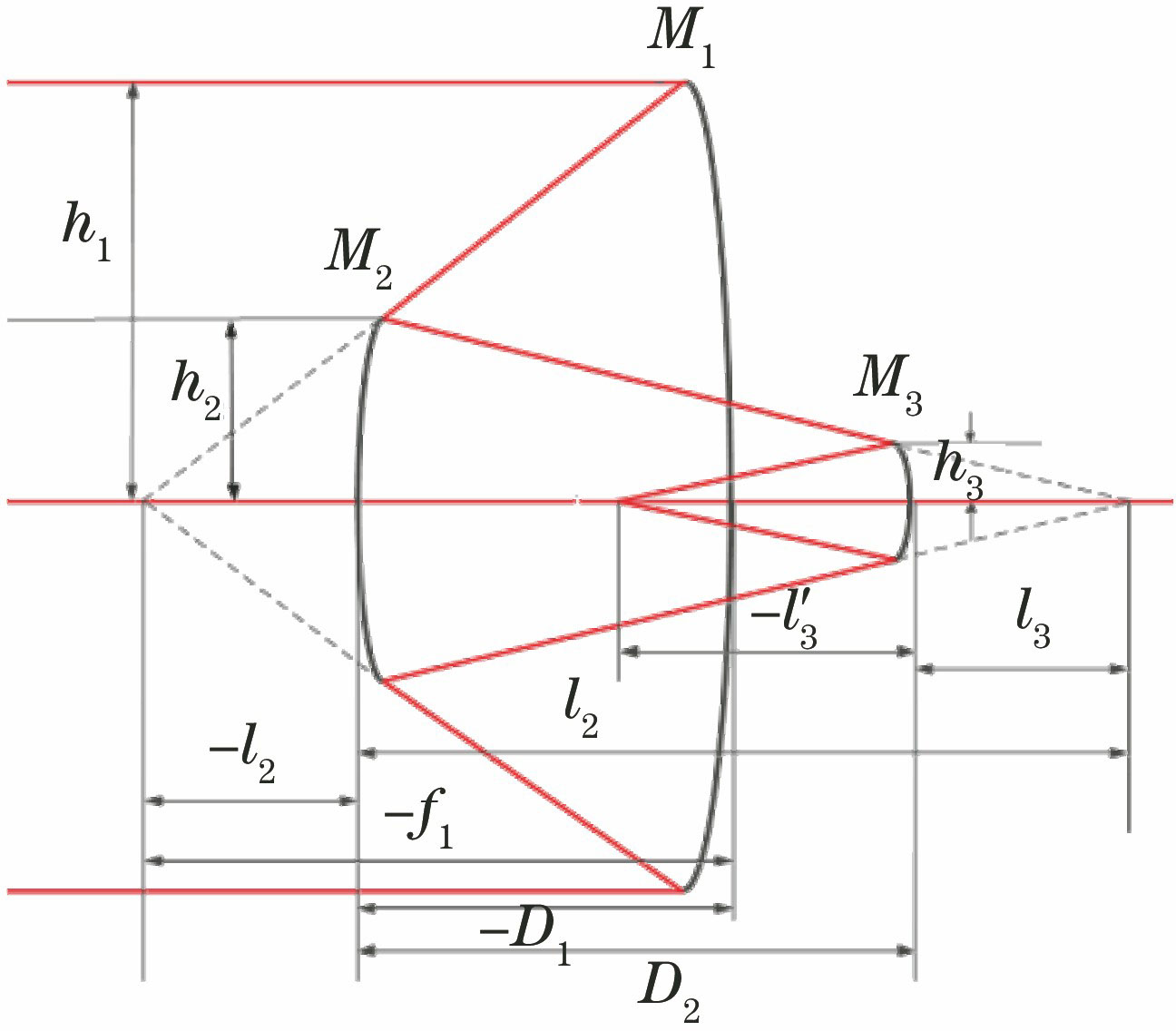
    Fig. 1. Structure of coaxial tri-reflection optical system
    Optical system structure
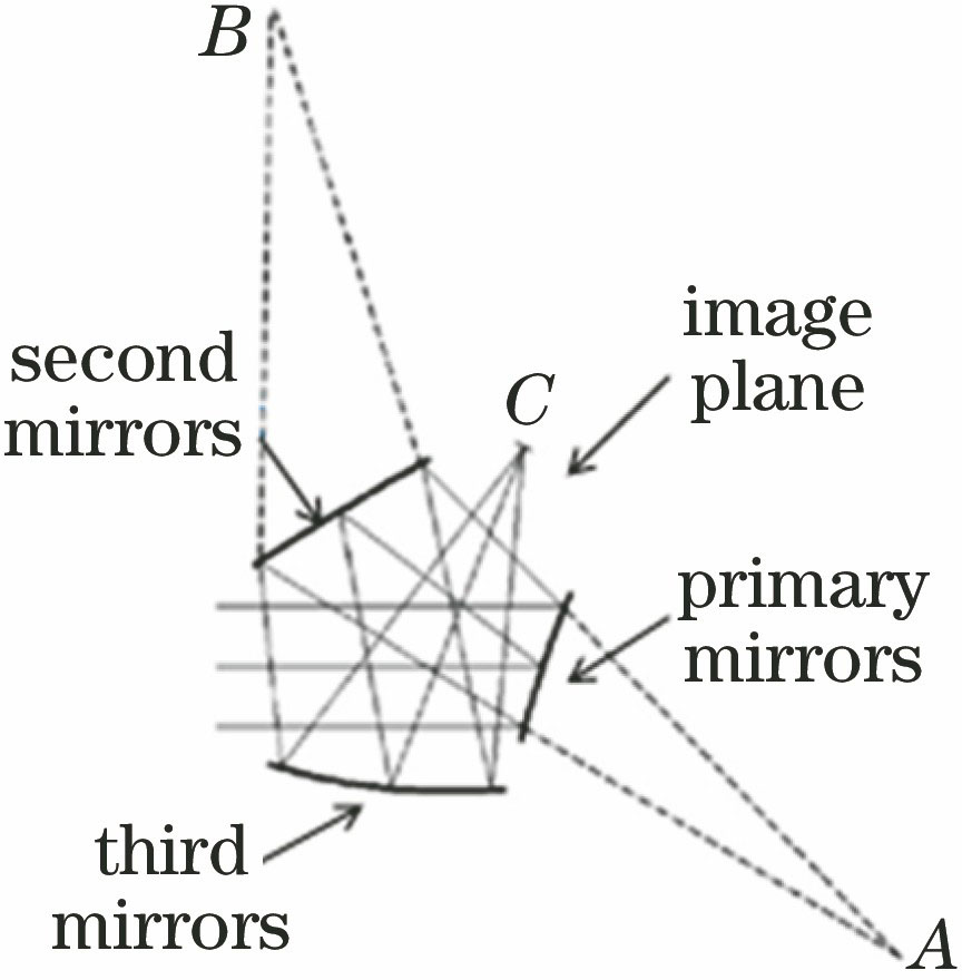
    Fig. 2. Optical system structure
    Optical structural diagram of non-central obscure design
    Fig. 3. Optical structural diagram of non-central obscure design
    Optical system without considering central obscuration. (a) Initial structural diagram; (b) modulation transfer function
    Fig. 4. Optical system without considering central obscuration. (a) Initial structural diagram; (b) modulation transfer function
    Optical structure and image quality evaluation function diagram of small off-axis optical system based on the first type of method. (a) Optical system structure diagram; (b) modulation transfer function; (c) root mean square spot
    Fig. 5. Optical structure and image quality evaluation function diagram of small off-axis optical system based on the first type of method. (a) Optical system structure diagram; (b) modulation transfer function; (c) root mean square spot
    Optical system without considering Seidel aberration. (a) Initial structural diagram; (b) modulation transfer function
    Fig. 6. Optical system without considering Seidel aberration. (a) Initial structural diagram; (b) modulation transfer function
    Optical structure and image quality evaluation function diagram of small off-axis optical system based on the second type of method. (a) Optical system structure diagram; (b) modulation transfer function; (c) root mean square spot
    Fig. 7. Optical structure and image quality evaluation function diagram of small off-axis optical system based on the second type of method. (a) Optical system structure diagram; (b) modulation transfer function; (c) root mean square spot
    Compact optical system structure and image quality evaluation function diagram based on the first type of method. (a) Optical system structure diagram; (b) modulation transfer function; (c) root mean square spot
    Fig. 8. Compact optical system structure and image quality evaluation function diagram based on the first type of method. (a) Optical system structure diagram; (b) modulation transfer function; (c) root mean square spot
    Optical system without considering Seidel aberration. (a) Initial structural diagram; (b) modulation transfer function
    Fig. 9. Optical system without considering Seidel aberration. (a) Initial structural diagram; (b) modulation transfer function
    Compact optical system structure and image quality evaluation function diagram based on the second type of method. (a) Optical system structure diagram; (b) modulation transfer function; (c) root mean square spot
    Fig. 10. Compact optical system structure and image quality evaluation function diagram based on the second type of method. (a) Optical system structure diagram; (b) modulation transfer function; (c) root mean square spot
    Systemstructureα1α2β1β2
    -、+、-(0,1)(0,1)(-¥,-1)(-1,0)
    -、+、-(0,1)(1,+¥)(0,+¥)(0,+¥)
    +、-、-(1,+¥)(1,+¥)(-¥,-1)(0,+¥)
    +、-、-(1,+¥)(0,1)(0,+¥)(-1,0)
    Table 1. Effects of contour parameters without intermediate imaging on optical system
    Systemstructureα1α2β1β2
    -、+、-(-¥,0)(1,+¥)(-1,0)(0,+¥)
    -、+、-(0,1)(-¥,0)(-¥,-1)(0,+¥)
    +、-、-(1,+¥)(-¥,-1)(0,+¥)(0,+¥)
    Table 2. Effects of contour parameters with intermediate imaging on optical system
    SurfaceSurface typeRadius /mmThickness /mm
    1Zernike-402.38-100.48
    2Zernike-160.94-100.48
    3Conic-191.77-132.10
    Table 3. Structure parameters of small off-axis optical system based on the first type of method
    SurfaceSurface typeRadius /mmThickness /mm
    1Zernike-474.48-150.18
    2Zernike-212.10-150.18
    3Conic-285.56-172.69
    Table 4. Structure parameters of small off-axis optical system based on the second type of method
    SurfaceSurface typeRadius /mmThickness /mm
    1Zernike-3902.92-181.04
    2Conic863.70122.77
    3Zernike-575.58-135.04
    Table 5. Compact optical system structure parameters based on the first type of method
    SurfaceSurface typeRadius /mmThickness /mm
    1Zernike-2045.95-132.27
    2Conic1640.29-132.27
    3Zernike-693.11-204.65
    Table 6. Compact optical system structure parameters based on the second type of method
    ParameterSmall off-axisangleCompact opticalsystem
    Class IClass IIClass IClass II
    MaximumRMS /μm6.5056.20014.83813.032
    20 lp/mm MTF>0.85>0.86>0.78>0.81
    Table 7. Optical system image quality evaluation function
    Junyang Li, Wenqiang Li, You Long, Liang Zhou, Yang Gao. Design of Off-Axis Three-Mirror Optical System Based on Free-Form Surface[J]. Laser & Optoelectronics Progress, 2020, 57(9): 092202
    Download Citation