
Bingshuang Yao, Xiaofei Zang, Zhen Li, Lin Chen, Jingya Xie, Yiming Zhu, Songlin Zhuang, "Dual-layered metasurfaces for asymmetric focusing," Photonics Res. 8, 830 (2020)
- Photonics Research
- Vol. 8, Issue 6, 830 (2020)
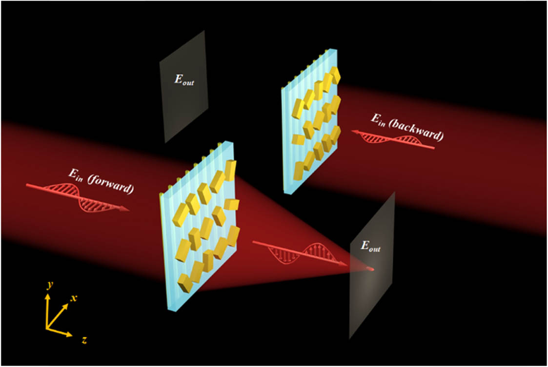
Fig. 1. Schematic of asymmetric focusing. Under the illumination of x y x
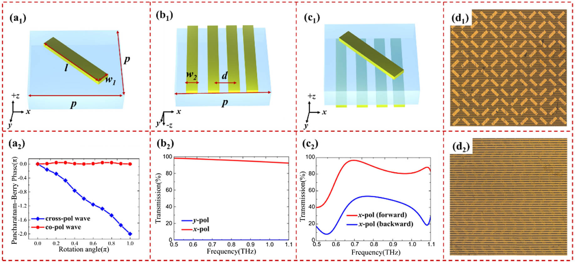
Fig. 2. Design of dual-layered metasurfaces: (a1) and (a2) schematic and the corresponding geometric phase of the microrod; (b1) and (b2) schematic and the corresponding transmission spectra of the metallic gratings; (c1) and (c2) schematic and the corresponding transmission spectra of the metasurface combined with metallic gratings; (d1) and (d2) optical images of the metasurface and metallic gratings.
Fig. 3. (a1)–(f1) Numerical simulation of electric field distributions in the x − z x x − y
Fig. 4. (a1)–(f1) The measured electric field distributions in the x − z x x − y
Fig. 5. Numerical simulation of asymmetric transmission with (a) and (b) longitudinal and (c) and (d) transversal multiple focal spots.
Fig. 6. (a1)–(c1) Schematics of a microrod, metallic gratings, and a unit cell of the directional device. The intersection angle between the long axis of the microrod and the x x T i j ( R i j ) i j ( i , j = x , y ) T i ( R i , i = x , y ) i
Fig. 7. (a1)–(f1) Numerical simulation of electric field distributions in the x − z y
Fig. 8. The calculated and measured electric field distributions in the x − z x
Fig. 9. The calculated electric field distributions in the x − z x
Fig. 10. Calculated efficiency of the directional device under the illumination of x
Fig. 11. Schematic of multiple transmissions from the dual-layered metasurfaces.
Fig. 12. Comparison of the numerical (blue curves) and experimental (red curves) focusing properties: (a)–(c) the corresponding electric field distributions at x = 0
Fig. 13. Schematics for the extinction ratio defined as (a) T E y / T E x T E y 1 / T E y 2
Fig. 14. (a1)–(c1) Calculated electric field ( | E y | 2 ) x − z x
|
Table 1. Size of the Focal Point
|
Table 2. Comparison Between the Diffraction Limit in Theory and the FWHM of the Focal Spots
|
Table 3. Extinction Ratio Between
|
Table 4. Extinction Ratio Between the Forward and Backward Directions
|
Table 5. Extinction Ratio for the Directional Device with Two Focal Spots


Set citation alerts for the article
Please enter your email address

© Copyright 2018-2021 | Chinese Laser Press. All Rights Reserved 沪ICP备15018463号-20