1Terahertz Technology Innovation Research Institute, Terahertz Spectrum and Imaging Technology Cooperative Innovation Center, Shanghai Key Laboratory of Modern Optical System, University of Shanghai for Science and Technology, Shanghai 200093, China
2Shanghai Institute of Intelligent Science and Technology, Tongji University, Shanghai 200092, China
Asymmetric transmission, defined as the difference between the forward and backward transmission, enables a plethora of applications for on-chip integration and telecommunications. However, the traditional method for asymmetric transmission is to control the propagation direction of the waves, hindering further applications. Metasurfaces, a kind of two-dimensional metamaterials, have shown an unprecedented ability to manipulate the propagation direction, phase, and polarization of electromagnetic waves. Here we propose and experimentally demonstrate a metasurface-based directional device consisting of a geometric metasurface with spatially rotated microrods and metallic gratings, which can simultaneously control the phase, polarization, and propagation direction of waves, resulting in asymmetric focusing in the terahertz region. These dual-layered metasurfaces for asymmetric focusing can work in a wide bandwidth ranging from 0.6 to 1.1 THz. The flexible and robust approach for designing broadband asymmetric focusing may open a new avenue for compact devices with potential applications in encryption, information processing, and communication.
1. INTRODUCTION
Asymmetric transmission is defined as the difference in the total transmission between the forward and backward directions, exhibiting great potential applications such as directionally sensitive beam splitting [1,2], multiplexing [3], communications [4], and optical interconnection [5]. A typical method for asymmetric transmission is to break the time-reversal symmetry using an external magnetic field [6], time-varying component [7,8], or nonlinear materials [9], leading to a topological-protected edge mode (nonreciprocal transmission). Although this nonreciprocal edge mode is immune to backscattering, it suffers from complicated materials, external biases, and bulk configurations. Based on the conventional passive and linear materials (chiral metamaterials [10–14], asymmetric metallic gratings [15], traditional polarization devices [16], and photonic crystals [17]), the reciprocal asymmetric transmission is realized by manipulating the propagation direction of electromagnetic (EM) waves.
Metasurfaces, two-dimensional counterparts of metamaterials, can tailor the propagation direction, phase, and polarization of EM waves, providing a platform to manipulate asymmetric transmission in multiple degrees of freedom, i.e., polarization and phase modulation. Benefiting from the superior capability in the local manipulation of the wavefront of EM waves, a plethora of applications such as metalenses [18–26], wave plates [27–30], vortex beam convertors [31–33], and holograms [34–39] have been demonstrated. Nevertheless, devices based on a single-layered metasurface show symmetric transmission, i.e., identical transmission between the forward and backward directions. Recently, multilayered plasmonic metasurfaces have been proposed to demonstrate the asymmetric transmission. For example, Frese et al. [40] and Chen et al. [41] designed dual/triple-layered plasmonic metasurfaces to realize an asymmetric meta-hologram and directional Janus, respectively. Sun et al. [42] reported asymmetric dual-frequency meta-holograms based on a triple-layered transmissive metasurface. These metasurface-based asymmetric devices work in a narrow band because of their resonant unit cells. In addition, study on metasurface-based asymmetric focusing is limited. Here we propose and experimentally demonstrate the broadband asymmetric focusing in the terahertz (THz) region triggered by simultaneous manipulation of the propagation direction, phase, and polarization of THz waves. This directional device for asymmetric focusing consists of a geometric metasurface (with a nonresonant unit cell) and metallic gratings. Unlike previously demonstrated resonant metasurfaces with different structured unit cells, the geometric metasurface consists of identical microrods, and the manipulation of phase, polarization, and energy flux is realized by rotating the microrods (to generate geometric phase). Our designed dual-layered metasurfaces for asymmetric focusing can work in a wide bandwidth ranging from 0.6 to 1.1 THz. The approach for designing directional meta-devices may provide a robust platform in developing future high-performance devices that can manipulate EM waves in multiple degrees of freedom.
Sign up for Photonics Research TOC. Get the latest issue of Photonics Research delivered right to you!Sign up now
2. DESIGN AND METHOD
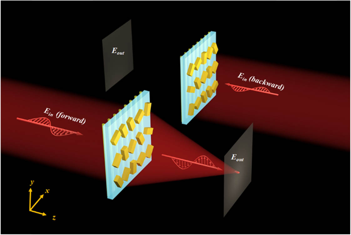
Figure 1 shows the schematic of an asymmetric focusing device. Upon the illumination of -polarized THz waves in the forward direction, a focal point with orthogonal polarization is observed after the dual-layered metasurfaces. In contrast, for backward incidence, the focal point is not generated, leading to asymmetric focusing. This directional device consists of a geometric metasurface with spatially rotated microrods and metallic gratings, which act as a linear polarizer that can transmit -polarized THz waves and reflect -polarized THz waves. The geometric metasurface is designed to simultaneously control the phase (for focusing) and polarization (for polarization rotation), generating a focal point with orthogonal polarization relative to incident THz waves. Since a linearly polarized THz beam consists of left-handed circularly polarized (LCP) and right-handed circularly polarized (RCP) components with the same amplitude, two opposite phase profiles [see Eq. (1)] should be required to focus both the LCP and RCP components: where is the focal length and is wavelength. Therefore, the focused LCP and RCP components [induced by phase modulations in Eq. (1)] with the same amplitude can be combined into a linearly polarized focal spot. Another bulk phase that can be generated by rotating each microrod with an angle of should be introduced into the geometric metasurface to rotate the polarization orientation of the focal spot. Therefore, the desired phase profile of the geometric metasurface is governed by where is the polarization rotation angle of the focal spot.
Figure 1.Schematic of asymmetric focusing. Under the illumination of -polarized THz waves in the forward direction, a -polarized focal spot is observed, while the focal spot is not generated for backward -polarized incidence.
To manipulate the incident THz waves based on geometric phase, each microrod should be designed as a quasi-perfect half-wave plate. The optimized structure parameters of a gold microrod are as follows: the width and length of the rods are μ and μ [see Fig. 2(a1)], and the period is 170 μm. Under the illumination of circularly polarized THz waves, the transmitted THz waves will contain two parts: one is the co-polarized THz waves, and the other is the cross-polarized THz waves. When the microrod is rotated counterclockwise/clockwise with an angle , the cross-polarized THz waves will be added with an additional phase delay of as shown in Fig. 2(a2). Figure 2(b1) shows the schematic of metallic gratings where the long side of each grating is along the axis. The width and period of these metallic gratings are 20 μm and 40 μm, respectively. As shown in Fig. 2(b2), the transmission for the incident -polarized THz waves is much higher than that of the incident -polarized THz waves. By introducing a geometric metasurface (with gold microrods) and metallic (gold) gratings [on the other side of the polyimide film (with permittivity of )], asymmetric transmission is realized [see Figs. 2(c1) and 2(d2)]. For forward -polarized incidence, the transmission is more than 82%, ranging from 0.6 to 1.1 THz, while it is lower than 52% under the the illumination of -polarized THz waves from the backward direction, demonstrating an asymmetric transmission that can work in a broad bandwidth.
Figure 2.Design of dual-layered metasurfaces: (a1) and (a2) schematic and the corresponding geometric phase of the microrod; (b1) and (b2) schematic and the corresponding transmission spectra of the metallic gratings; (c1) and (c2) schematic and the corresponding transmission spectra of the metasurface combined with metallic gratings; (d1) and (d2) optical images of the metasurface and metallic gratings.
Figure 3 shows numerical simulations of asymmetric focusing. The size of this final metasurface composed of microrods is . Based on the finite-difference time-domain (FDTD) method, the electric field distributions of asymmetric focusing are calculated and shown in Figs. 3(a1)–3(f2). For simplicity, we calculated (and measured) electric field distributions at 0.6, 0.85, and 1.1 THz to show the broadband characteristic of our directional devices. Figure 3(a1) shows the electric field distribution of -polarized transmission for forward THz waves at . The polarization of one focal spot observed at is along the axis, which is orthogonal to the polarization of the incident THz waves, while the focal spot [see Fig. 3(b1)] is not generated for backward incidence, leading to asymmetric focusing. Here the mechanism of the asymmetric focusing can be understood as follows: for forward incidence, the -polarized THz waves are almost completely transmitted through the metallic gratings and simultaneously interact with the metasurface (microrods with different orientations). Therefore, the transmitted -polarized THz waves are partly converted into -polarized THz waves and simultaneously focused into a focal spot. In contrast, for backward incidence, a portion of the waves interact with the metasurface and are converted into -polarized THz waves. Then the converted waves are reflected completely after interacting with metallic gratings. The other part of nonconverted (-polarized) THz waves can pass through metallic gratings. However, the nonconverted THz waves are not modulated by the metasurface and thus cannot be focused into a focal spot for backward waves. The detailed mechanism of asymmetric focusing under the illumination of -polarized (and -polarized) THz waves in the forward and backward directions is given in Appendix A. Figures 3(a2) and 3(b2) show electric field distributions in the plane (). For forward transmission, a circularly shaped focal spot is observed at the real focal plane (), while it cannot be generated (at ) for the backward case [see Figs. 3(a2) and 3(b2)]. When THz (1.1 THz), a focal point located at () with polarization along the axis is observed for forward incidence as shown in Figs. 3(c1) and 3(e1). In comparison with Figs. 3(a1), 3(c1), and 3(e1), the distance between the focal spot and the device is getting longer and longer due to the chromatic aberration. The focal spot cannot be generated for backward incidence [see Figs. 3(d1) and 3(f1)]. The corresponding electric field distributions in the plane are shown in Figs. 3(c2)–3(f2), demonstrating asymmetric focusing between the forward and backward directions. The calculated efficiencies of the directional device at these three frequencies are 23.03%, 26.7%, and 21.34%, respectively. The calculated electric field distributions and the performances (broadband property, size, and excitation ratio of the focal spot) of this directional device are given in Appendix B and Appendix C, respectively. In addition, the focusing properties under the illumination of THz waves with different incident angles are shown in Appendix D.
Figure 3.(a1)–(f1) Numerical simulation of electric field distributions in the plane under the illumination of -polarized THz waves in the forward/backward direction at 0.6, 0.85, and 1.1 THz; (a2)–(f2) the corresponding electric field distributions in the plane.
In experiment, we utilize near-field terahertz microscopy (NSTM) [26,43] to detect field distributions. The position of the THz source and THz tip are fixed while the sample is rotated along the axis to measure the field distributions under the illumination of THz waves in the forward and backward directions. For forward -polarized incidence (with working frequency of 0.6 THz), a focal point is generated with polarization along the axis (at ) as shown in Fig. 4(a1). In contrast, the focal spot is not generated for backward incidence [see Figs. 4(b1)], resulting in asymmetric focusing. Figures 4(c1)–4(f1) show the measured electric field distributions at 0.85 THz and 1.1 THz, respectively. Under the illumination of -polarized THz waves in the forward direction, a focal spot located at 3.5 mm (or 5.5 mm) is observed as shown in Figs. 4(c1) and 4(e1), while this focal spot cannot be generated for backward incidence [see Figs. 4(d1) and 4(f1)]. The measured electric field distributions in the plane at , , are shown in Figs. 4(a2)–4(f2), and they also reveal the asymmetric functionality. The measured efficiencies of the directional device at , 0.85, and 1.1 THz are 20.6%, 25.3%, and 20.3%, respectively. The experimental results are matched well with the numerical simulations, except for a slight discrepancy, which can be attributed to the fabrication error and nonperfect half-wave plate of each microrod. In addition, the signal-to-noise ratio of the THz source (in the experiment) decreases with the increase of the frequency, and thus the focal spot is distorted in comparison with the case in simulation. The measured electric field distributions and the performances (size and excitation ratio of the focal spot) of the directional device are given in Appendix B and Appendix C, respectively.
Figure 4.(a1)–(f1) The measured electric field distributions in the plane under the illumination of -polarized THz waves in the forward/backward direction at 0.6, 0.85, 1.1 THz; (a2)–(f2) the corresponding electric field distributions in the plane.
Our approach can not only manipulate asymmetric transmission with one focal point but also enable the capability to harness the multiple focal points with functionality of asymmetric transmission. We numerically demonstrate the asymmetric transmission with longitudinal and transverse multiple focal spots as shown in Fig. 5. The corresponding phase profile requirements of the longitudinal and transverse multiple focal spots are written as where and have the same formula as shown in Eq. (1) but different focal length [ (focal length) for and , while (focal length) for and ]. and . The designed parameters are , , , and . Figure 5(a) shows the electric field distribution of the asymmetric transmission of longitudinal multiple focal spots upon the illumination of -polarized THz waves (at 0.85 THz) from the forward direction. Two separated focal points located at and are observed along the longitudinal direction. Here the discrepancy in focus spot position between theoretical design and numerical simulation results from the nonperfect half-wave plate of the microrods. When the -polarized THz waves interact with the geometric metasurface (with the phase profile shown in ), two transversely distributed focal points located at (, ) and (, ) are generated as shown in Fig. 5(c). These two focal points are not generated for backward incidence as shown in Figs. 5(b) and 5(d). The calculated efficiencies of the asymmetric transmission with longitudinal and transverse focal spots are 23.93% and 25.35%. The calculated electric field distributions and the performances (excitation ratio of the focal spot) of the directional device are given in Appendix B and Appendix C, respectively.
Figure 5.Numerical simulation of asymmetric transmission with (a) and (b) longitudinal and (c) and (d) transversal multiple focal spots.
The approach can be utilized to design ultrathin and ultraflat geometric metasurfaces by simultaneously controlling the polarization, phase, and transmission direction in all spatial dimensions, leading to unprecedented capabilities in developing multifunctional components and ultrathin systems. Typically, the asymmetric functionality of our designed metasurfaces can be traditionally realized by putting together a lens, a half-wave plate, and a linear polarizer. However, the conventional devices should typically be thick enough and exhibit certain surface topography to ensure the gradual phase accumulation (along the propagation direction) to realize the desired wave-manipulating functionalities. The thickness of these traditional THz elements is up to the order of centimeters, resulting in a large and bulky functional device. Since device miniaturization and system integration are two continuing trends for next-generation integration-optics applications, our designed directional device opens a new avenue to address the aforementioned issues. The thickness of the metasurface and metallic gratings is 0.15 μm, while it is 30 μm for the spacer (polyimide). The total thickness of the device is 30.3 μm, which is an order of ( is the central working wavelength of the designed device). Therefore, the uniqueness and robustness of our proposed approach may provide a platform for designing future multifunctional and ultracompact devices. The sample fabrication is given in Appendix E. In addition, the efficiency plays an important role for device performance. The efficiency of the directional device is more than 20% [in simulation (see Fig. 10)] ranging from 0.6 to 1.1 THz. For the traditional devices, the efficiency of the THz lens (half-wave plate and linear polarizer) is about 52% (75% and 90%). Therefore, the total efficiency of the asymmetric focusing (realized by traditional devices) is about 35%. In comparison with the traditional bulk devices, our designed directional device not only shows a comparable performance in the efficiency but also enables the ability to design ultrathin devices.
From the practical point of view, some other distinct properties of the designed directional device are of great interest. Unlike traditional asymmetric transmission, which only controls the propagation direction of EM waves, the developed directional device can simultaneously control the polarization, phase, and transmission direction, leading to a directional metalens. As is well known, lenses can be applied for imaging. Recently, various types of metalenses such as dual-polarity plasmonic metalenses [18,19], achromatic metalenses [23,44], metalens arrays [45], and polarization-dependent metalenses [26,46] have been developed for imaging. However, all of the previous metalenses are symmetric in the forward and backward directions. The developed directional metalens can be applied for unidirectional imaging, which means that we can grab information/imaging from the “enemy” side and avoid our own information being detected. As a result, the designed ultrathin device can have an immediate impact on information security and cloaking. Moreover, the proposed approach can be extended to design asymmetric transmission with multiple focal points, while a traditional lens generates only one focal point. Therefore, the flexible design will enable the directional metalens with unprecedented functions that are impossible to achieve by traditional lenses. Due to the simplicity and robustness of the method, our approach can be easily extended into the visible and IR frequency regions by designing the metasurface and metallic gratings with proper sizes, i.e., the same structure with reduced size. While remarkable progress has been achieved, great challenges, i.e., further enhancement of the focusing efficiency and asymmetric focusing under oblique incidence, exist that provide new opportunities for future studies.
In conclusion, we have proposed and experimentally demonstrated an approach to realizing asymmetric focusing in the THz region. Based on a geometric metasurface and polarization-selective gratings, a focal spot is observed under the illumination of -polarized THz waves in the forward direction, while this focal spot is not generated for backward incidence. This metasurface-based directional device works in a broad bandwidth ranging from 0.6 to 1.1 THz. The robust approach can be also extended to design asymmetric transmission with multiple focal points. The presented dual metasurfaces are a powerful tool that can not only flexibly control the wavefront of EM but also open a new window to manipulate the propagation direction of EM waves.
APPENDIX A: PRINCIPLE OF ASYMMETRIC FOCUSING
Metasurface with Linearly Polarized Focusing and Polarization Rotation
We assume a (transmission-type) metasurface with the long axis of each metallic microrod along the axis. Under the normal illumination of a linearly polarized (-polarized) THz beam, the polarization of the transmitted beam is the same as the incident THz waves. The Jones vector of the transmitted beam can be written as If each of the microrods is rotated counterclockwise with an angle of , the transmitted beam will contain two parts. One part is a polarization-rotated (converted) beam in which the polarization is rotated counterclockwise with an angle (). The other part is a co-polarized (nonconverted) beam without polarization rotation. It can be understood as follows: under the illumination of a linearly polarized THz beam, the LCP component is partially converted into an RCP THz beam with an abrupt phase delay of , while the RCP component is partially converted into LCP THz waves with an additional phase delay of . The transmitted electric field for the converted LCP and RCP beams can be written as where is the conversion efficiency. Both of these converted (LCP/RCP) components can be combined to a linearly polarized THz beam because of the same transmission intensity. The electric field is expressed as follows: As a consequence, the polarization of the converted (linearly polarized) THz beam is rotated counterclockwise with an angle of , which is realized by counterclockwise rotation of each microrod with an angle of .
To enable the functionality of focusing, two opposite phase profiles are introduced to focus both the LCP and RCP components of the converted THz waves. One phase profile is ( is the focal length), and the other phase profile is . Here the first phase profile can focus (defocus) the RCP (LCP) component of the converted THz waves, while the second phase profile can focus (defocus) the LCP (RCP) component of the converted THz waves. The Jones vector of the converted (polarization-rotated) beam under the modulation of the aforementioned two opposite phase profiles can be given as [21] The above equation can also be expressed as follows: Accordingly, the required phase distribution for our proposed metalens is governed by It should be noted that is the rotation angle of polarization, while and are the required phase profiles for focusing the LCP and RCP components. Therefore, under the illumination of a linearly polarized THz beam, it can be focused into a linearly polarized focal point with the corresponding polarization rotated with an angle of . Here we neglect the coefficient of conversion efficiency because it does not affect the total phase profile as shown in Eq.?(6).
Metasurface Combined with Metallic Gratings for Asymmetric Focusing
Figure?6 shows the schematics [see Figs.?6(a1)–6(c1)], transmission, and reflection of a microrod, metallic gratings, and a unit cell of the directional device under the illumination of linearly polarized THz waves. Figures?6(a2)–6(a4) illustrate the co-polarized, cross-polarized, and total transmission/reflection of the microrod under the illumination of linearly polarized THz waves. It should be noted that the microrod enables functionality of a quasi-perfect half-wave plate, and the intersection angle between the long axis of the microrod and the axis is 45°. Therefore, under the illumination of -polarized (or -polarized) THz waves, the transmitted/reflected waves contain two parts: one has the same polarization as the incident THz waves, and the other has the cross-polarization. As shown in Fig.?6(a1), the single-layered metasurface (microrods) shows perfect symmetry to the incident THz waves in the forward and backward directions. As a consequence, the transmission (or reflection) of the microrod upon the illumination of linearly polarized THz waves in the forward direction is the same as that for backward incidence as shown in Figs.?6(a2)–6(a4). For metallic gratings [see Fig.?6(b1)], the co-polarized transmission of -polarized THz waves for forward and backward incidence is more than 86%, ranging from 0.6 to 1.1?THz, while the co-polarized reflection in this case is less than 8% as shown in Fig.?6(b2). For -polarized incidence, the THz wave is reflected completely [ in Fig.?6(b2)] without transmission. In addition, the cross-polarized transmission and reflection are all near zero [see Fig.?6(b3)]. Therefore, the designed metallic gratings with a long axis along the axis can block -polarized THz waves and transmit -polarized THz waves as shown in Fig.?6(b4).
Figure 6.(a1)–(c1) Schematics of a microrod, metallic gratings, and a unit cell of the directional device. The intersection angle between the long axis of the microrod and the axis is 45°, while the long axis of gratings is along the axis. (a2)–(a4) The co-polarized/cross-polarized/total transmission and reflection of the microrod under the illumination of linearly polarized THz waves. (b2)–(b4) The co-polarized/cross-polarized/total transmission and reflection of the metallic gratings under the illumination of linearly polarized THz waves. (c2)–(c4) The co-polarized/cross-polarized/total transmission and reflection of the unit cell of the directional device under the illumination of linearly polarized THz waves. is the transmission (reflection) of the -polarized THz waves under the illumination of -polarized THz waves . is the total transmission (total reflection) under the illumination of -polarized THz waves.
Figure 7.(a1)–(f1) Numerical simulation of electric field distributions in the plane under the illumination of -polarized THz waves in the forward direction at 0.6, 0.85, and 1.1 THz; (a2)–(f2) the calculated electric field distributions for backward incidence.
Figure?7 shows the calculated electric field distributions of the directional device under the illumination of -polarized THz waves in the forward and backward directions. As shown in Figs.?7(a1) and 7(b1), the focal spot cannot be generated for forward incidence. In contrast, an -polarized focal point is observed for backward incidence [see Figs.?7(a2) and 7(b2)], indicating that a portion of the -polarized THz waves (for backward incidence) are converted into -polarized THz waves and simultaneously focused into a focal spot. For (1.1?THz), an -polarized focal point can also be observed for backward incidence, while it is not generated for forward incidence [see Figs.?7(c1)–7(f1) and 7(c2)–7(f2)]. In comparison with Figs.?7(b2), 7(d2), and 7(f2), the distance between the focal spot and the device is getting longer and longer, which can be attributed to the chromatic aberration.
APPENDIX B: ELECTRIC FIELD (Ex) DISTRIBUTIONS OF THE DIRECTIONAL DEVICE
Figure?8 shows the calculated and measured electric field distributions of the directional device (that can unidirectionally generate a -polarized focal point) under the illumination of -polarized THz waves in the forward and backward directions. As shown in Figs.?8(a1), 8(c1), and 8(e1), no focal spot can be observed under the illumination of -polarized THz waves in the forward direction. In experiment, the corresponding electric field distributions in Figs.?8(b1), 8(d1), and 8(f1) also demonstrate that there is no (-polarized) focal spot. For backward incidence, the designed directional device cannot modulate nonconverted THz waves into a focal spot as shown in Figs.?8(a2)–8(f2).
Figure 8.The calculated and measured electric field distributions in the plane under the illumination of the -polarized THz waves from the (a1)–(f1) forward and (a2)–(f2) backward directions at 0.6, 0.85, and 1.1 THz.
Figure 9.The calculated electric field distributions in the plane under the illumination of the -polarized THz waves in the (a1), (b1) forward and (a2), (b2) backward directions at 0.85 THz.
Figure?10 shows the calculated efficiency of our designed device under the illumination of -polarized THz waves in the forward direction. The efficiency is more than 20% ranging from 0.6 to 1.1?THz, demonstrating a broadband directional device.
Figure?11 shows the schematic of multiple transmissions from the dual-layered metasurfaces. For forward -polarized incidence, the total output THz waves are the superposition of all the transmitted THz waves passing through the microrods. The transmitted THz waves are expressed as follows:
Figure 11.Schematic of multiple transmissions from the dual-layered metasurfaces.
Figure 12.Comparison of the numerical (blue curves) and experimental (red curves) focusing properties: (a)–(c) the corresponding electric field distributions at in the focal plane.
For traditional asymmetric transmission, the extinction ratio is defined as the ratio of the transmission coefficient for forward incidence to that for backward incidence. Therefore, the extinction ratio of the asymmetric focusing in our paper can also be analogously defined as the ratio of the component for forward -polarized incidence to that for backward incidence [40] [extinction and ] as shown in Fig.?13(b). Here and are defined as the transmission of the component under the illumination of -polarized THz waves in the forward and backward directions. In this case, the extinction ratios at 0.6, 0.85, and 1.1?THz are 36.6:1, 81.5:1, and 76.2:1 as shown in Table?4. In the experiment, the corresponding extinction ratios are 17:1, 71:1, and 15.5:1 at 0.6, 0.85, and 1.1?THz.
Extinction Ratio Between the Forward and Backward Directions
Frequency (THz)
0.6
0.85
1.1
Sim. extinction ratio
36.6:1
81.5:1
76:1
Exp. extinction ratio
17:1
71:1
15.5:1
The extinction ratios (defined as the ratio of the transmission coefficient between and components under the illumination of -polarized THz waves in the forward direction) of the directional device with two unidirectional focal points are shown in Table?5. They are 5.4:1 and 6:1, respectively. For the extinction ratio, defined as the ratio of the transmission coefficient for forward waves to that for backward waves, they are 82:1 and 38:1 as shown in Table?5.
Extinction Ratio for the Directional Device with Two Focal Spots
Extinction Ratio
Longitudinal
Transversal
5.4:1
6:1
82:1
38:1
APPENDIX D: PERFORMANCES OF THE DIRECTIONAL DEVICE UNDER THE ILLUMINATION OF THz WAVES WITH DIFFERENT INCIDENT ANGLES
Figure?14 shows the calculated electric field distributions of the directional device under the illumination of -polarized THz waves with different incident angles in the forward and backward directions. (The corresponding electric field distributions at and 1.1?THz show the same trend as in Fig.?14.) For incident angles ranging from 10° to 30°, the focal spot is more and more?deviated from the center of the device and shifted to the blow with the increase of incident angle [see Figs.?14(a1)–14(c1)]. When the incident THz waves with a tilted wavefront (nonzero incident angle) interact with the directional device, the original position for generating the constructive interference (at and ) is shifted downward, and thus the focal spot is?deviated to the blow. Since the original geometric phase with respect to normally incident THz waves shows circular symmetry, it cannot keep the circular symmetry under the illumination of -polarized THz waves with nonzero incident angles. Therefore, the deviated focal spots will inevitably be distorted as shown in Figs.?14(a1)–14(c1). For backward incidence, no focal spot can be observed [see Figs.?14(a2)–14(c2)].
Figure 14.(a1)–(c1) Calculated electric field distributions in the plane under the illumination of -polarized THz waves (with different incident angles) in the forward directions at 0.85 THz; (a2)–(c2) the calculated electric field distributions for backward incidence. Insets show the schematics for the incident THz waves with a tilted wavefront.
We fabricated the directional device based on traditional photolithography. The AZP5214 photoresist (with thickness of 1.6?μm) was spun (with spin speed of 3000 r/min) onto one side of the polyimide film. Then a mask was utilized for exposure processing. After the metal coating and ultrasonic striping, gold microrods were formed, resulting in a metasurface. The gold gratings can also be fabricated on the other side of the polyimide film by repeating the same processing.