Laser communication using photons should consider not only the transmission environment’s effects, but also the performance of the single-photon detector used and the photon number distribution. Photon communication based on the superconducting nanowire single-photon detector (SNSPD) is a new technology that addresses the current sensitivity limitations at the level of single photons in deep space communication. The communication’s bit error rate (BER) is limited by dark noise in the space environment and the photon number distribution with a traditional single-pixel SNSPD, which is unable to resolve the photon number distribution. In this work, an enhanced photon communication method was proposed based on the photon number resolving function of four-pixel array SNSPDs. A simulated picture transmission was carried out, and the error rate in this counting mode can be reduced by 2 orders of magnitude when compared with classical optical communication. However, in the communication mode using photon-enhanced counting, the four-pixel response amplitude for counting was found to restrain the communication rate, and this counting mode is extremely dependent on the incident light intensity through experiments, which limits the sensitivity and speed of the SNSPD array’s performance advantage. Therefore, a BER theoretical calculation model for laser communication was presented using the Bayesian estimation algorithm in order to analyze the selection of counting methods for information acquisition under different light intensities and to make better use of the SNSPD array’s high sensitivity and speed and thus to obtain a lower BER. The counting method and theoretical model proposed in this work refer to array SNSPDs in the deep space field.
1. INTRODUCTION
As compared with traditional microwave radio communication, laser communication using optical pulses as information carriers has many advantages including high bit rate, no frequency restrictions, and strong resistance to electromagnetic interference [1,2]. In the past 30 years, free-space laser communication technology has developed rapidly [3,4]. NASA’s Lunar Laser Communication Demonstration (LLCD) was also demonstrated in 2013 between the Lunar Atmosphere and Dust Environment Explorer (LADEE) and the ground station [5–7]. The demonstration achieved almost an entire order of magnitude higher data rate than the radio communication demonstration. However, due to the inherent volume and weight limitations of any potential satellite laser receiver in a deep space downlink communication system, the amount of energy emitted by a laser is also currently limited [8]. Most of the photons reaching photodetectors on the ground were at the single-photon level because of optical pulse signal scattering and absorption by atmospheric turbulence. Semiconductor photodetectors such as single-photon avalanche diodes (SPADs) [9,10] are usually used for ground terminals’ photodetectors. However, because ordinary semiconductor photodetectors do not have sufficiently high sensitivity, the communication quality is limited. Superconducting nanowire single-photon detectors (SNSPDs), a new type of high-sensitivity photodetector, not only have detection sensitivity up to the single-photon level but also have excellent performance qualities such as high efficiency, low dark count, high time accuracy, and short recovery time. In recent years, research on laser communication for SNSPDs in photon-counting communications has been increasing, and good progress has been made [11–14].
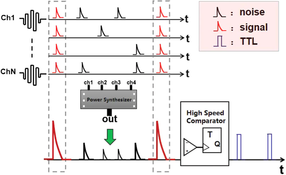
The SNSPD was biased slightly below the superconducting critical current, and a rapidly rising then exponentially decaying electrical pulse was captured on the readout circuit when the nanowires absorbed photons. By amplifying the pulse signal with an amplifier, the arrival of the photons that transmit information can be identified. However, traditional laser communication based on an SNSPD is limited by the detector’s recovery time [15], which makes it impossible to increase the communication rate. On the other hand, the inability to distinguish between dark noise and signal photons in the channel will result in a higher bit error rate (BER). In order to overcome these two defects, an SNSPD has been adopted with an array structure. The array SNSPD has high system detection efficiency (SDE), high counting rate (CR), and photon number resolving [16–19]. By combining this with an external readout circuit, an enhanced photon communication method based on photon number resolving is proposed. It is well-known that noise in optical communications can be regarded as random responses by the SNSPD, while photons in optical pulse transmitting data are time dependent. As shown in Fig. 1, each pixel of the superconducting detector array outputs a response electric pulse after detecting the incident photon, and each pixel outputs the response simultaneously and independently. The output electric pulse will produce a difference in amplitude after the superposition operation. When there is only a single-pixel response, the voltage pulse amplitude is the smallest. When there are multiple pixel responses, the superimposed voltage pulse amplitude increases linearly according to the number of response pixels, thereby exhibiting the photon number analysis function. Thus, the signal pulse will correspond to a higher amplitude, while the random noise response pulse generally corresponds to a lower amplitude height. The noise can be filtered out by setting the high-speed comparator’s threshold voltage.
Figure 1.Working principle of array SNSPD multi-channel simultaneous output.
2. ENHANCED PHOTON COMMUNICATION TEST WITH SNSPD ARRAY
Next, an experimental simulation was conducted. The four-pixel SNSPD was used in the experiment. Its detection efficiency was about 50% with a recovery time of 50 ns in the 1550 nm band. Figure 2 is the whole communication system’s schematic diagram. First, the data to be transmitted was converted into binary codes, and then binary codes of the data were converted into electrical signals through an arbitrary waveform generator. The output high level represents the “1” code in the binary codes, and the low level represents the “0” code in the binary codes. By operating the pulsed laser source in external trigger mode, the arbitrary waveform generator’s output electric signal was converted into an optical pulse signal, and the optical pulse was transmitted to the SNSPD array working at 2.3 K through the adjustable optical attenuator. Because the actual experimental conditions are limited, these experiments are based on fiber optic technology and use a variable optical attenuator (VOA) to adjust the light intensity reaching the detector, and they thus simulate the effect of communication distance on the system’s BER. The synchronous electric pulses of the SNSPD were amplified by a low-noise amplifier and transmitted to the power synthesis module strictly through the same length of coaxial line. The power synthesis module superimposed and degenerated the four input pulses into one output waveform, and the high-speed comparator converted the rapidly rising then exponentially attenuating electric pulse generated by the SNSPD into a transistor-transistor logic (TTL) signal. Finally, TTL signal was collected via computer-controlled oscilloscope and later decoded.
Sign up for Photonics Research TOC. Get the latest issue of Photonics Research delivered right to you!Sign up now
Figure 2.Schematic diagram of simulated optical communication system.
Figure 3 is the screen capture of a black-and-white picture transmitted to the oscilloscope at a certain time. The yellow waveform is the synchronization signal input by an arbitrary waveform generator to the external modulation port of the pulse laser, and the green waveform is the detection pulse output by the SNSPD. The delay between the green waveform and the synchronization signal was about 100 ns. Two likely reasons exist for this: the optical pulse was transmitted to the detector’s photosensitive surface at 2.3 K through a section of optical fiber, and the response electric pulse generated by the detector was then transmitted through a length of coaxial cable. The blue waveform is the TTL waveform of the SNSPD output signal after the shaping module. Results indicate that the SNSPD can generate an impulse response for each incoming signal-pulse photon without losing information. Figure 4 shows the intensity comparison diagram of each pixel after image transmission. Some pixels’ intensities are less than that of the original image. Analysis suggests that, due to detector efficiency limitations, the detector failed to respond to every signal pulse, or the output pulse amplitude was too low due to a deficiency of response pixels.
Figure 3.Yellow waveform is the synchronization signal input from an arbitrary waveform generator to a pulsed laser, the higher amplitude pulse on the left is the head of the transmitted data (easy to compare), the green waveform is output of the SNSPD that detects photons with data information and outputs electric pulses that rise rapidly and then decay exponentially (with a delay of about 100 ns), and the blue waveform is the TTL signal of SNSPD output waveform after the shaping module.
Figure 5 shows the contrast between the RGB color image and the original image. The BER of this communication was as low as , and only a few pixels appeared as snowflakes. In addition, for fixed binary data, coded modulation of 10, 20, 40, and 50 Mbps was performed. The curves of their changes with the light intensity were measured and analyzed as shown in Fig. 6. When the pulse repetition rate was low, the BER decreased when light intensity increased. However, when the pulse repetition frequency reached 40 Mbps and 50 Mbps, it took a certain time for each pixel of the SNSPD to recover from a resistive state to a superconducting state. During this recovery period, incident photons could not be detected, resulting in BER fluctuation. This phenomenon was more obvious with the light intensity increased, which also resulted in a very low BER at higher light intensity, but it can limit the performance advantages of the array SNSPDs at high speeds, so how to select the optimal enhanced photon-counting method under different light intensities is especially important.
Figure 5.Picture transmitted through the system (left) and the original picture (right).
Figure 6.Variation of BER with light intensity at different transmission frequencies. The transmission speeds of the black, red, blue, and pink curves were 10, 20, 40, and 50 Mbps, respectively. The detector was a four-pixel array SNSPD, detection efficiency was 50% at 1550 nm band, and the recovery time of the nanowires was 50 ns.
Therefore, the BER model of the enhanced photon-counting mode based on array SNSPDs needs to be analyzed. Based on the photon number resolving detection model of the SNSPD [20] and the above-mentioned counting methods [21,22], two errors in laser communication will be analyzed and addressed: the correct “1” code becomes the wrong “0” code, and the correct “0” code becomes the “1” code. The number of photons contained in the pulsed light emitted by the laser source obeys a Poisson distribution with parameter (average photon number of pulses). Suppose the system efficiency of SNSPD is and the number of pixels is . In order to simplify the analysis, assuming there is an even incidence of photons on each pixel, the average number of photons incident on a single pixel in a single pulse time is , and then the probability of detecting photons is For a single pixel, detection of the correct “1” code may be caused by signal photons, random dark counts, or a combination of the two. Removing the probability of these two factors not affecting the pixel, the probability that the pixel detects the “1” code can be obtained. For an -pixel array detector, the probability that pixels detect the correct “1” code is as follows: where DCR is the dark count of each detector pixel in units of cps (counts per second). In order to simplify the analysis, the dark count of each pixel is assumed to be the same. Equation (2) shows that the main factors affecting the conversion of correct “1” codes to “0” codes lie in the two parameters of light intensity () and detector efficiency ().
Similarly, due to the existence of dark counts in detectors, error codes will occur. The dark counts detected by SNSPD include the intrinsic dark noise of the detector and background photons introduced by the space optical environment. Therefore, when there is no signal light, the probability of an error “1” code generated by pixels in pixels of the detector is where is the modulation frequency of the signal pulse and DCR/f is the probability of generating dark counts per unit time, i.e., the probability of a wrong “1” code, while the original probability of a correct “0” code is . Thus, the probability of detecting the correct “0” codes by pixels of the -pixel array detector is as follows:
As mentioned above, simultaneous multi-pixel response is bound to cause information photons that arrive within the recovery time to go undetected, losing the high-speed performance advantages of array SNSPDs. In addition, lower-amplitude pulses due to light intensity and detector efficiency limitations may still be pulsed with information, and higher-amplitude counting will cause this portion of the low-amplitude signal pulse to be filtered out, resulting in information loss. In order to get the best count threshold, the Bayesian estimates are applied to this count mode selection, which has been widely used in artificial intelligence, quantum optical phase estimation [23–27], and other fields. Due to the uncertainty of random noise in this communication system, the Bayesian formulas are as follows: where , as shown in Eq. (2), denotes the conditional probability of the response of pixels when there is signal light (“1” code). , as shown in Eq. (3), denotes the conditional probability of the response of pixels when there is no signal light and only dark counting (“0” code).
The case of is focused on in this article, and subsequent calculations are based on the assumption of this prior probability; therefore we set , , and , so according to Eqs. (5) and (6) the posterior probabilities of and under four light intensities can be obtained. According to Fig. 7, when the light intensity is weak, a single pixel can respond correctly to the signal photon. When the signal intensity is increased to more than 3, only two pixels are needed for correct signal detection. When the intensity reaches 10, three pixels are needed to obtain the correct transmission information. For example, for a strong signal light, if reaches 30 or more, a four-pixel full response is required for counting.
Figure 7.Variation curves of posterior probabilities and with the number of pixels by Bayesian estimation under four light intensities. (a)–(d) represent , 3, 10, and 30.
Therefore, in order to obtain the best communication accuracy and speed, the following counting methods can be adopted: when , take 1 code; when , take 0 code, where takes the first values when . Thus, the BER can be expressed as
According to Eq. (7), the curves of the system’s BER obtained with different are shown as a function of light intensity in Fig. 8. The black curve is the BER curve of a traditional single-pixel SNSPD as a function of light intensity, which is obtained under the same conditions (detector efficiency, dark background count, transmission speed, etc.). We can thus choose a reasonable as the counting threshold in different light intensity regions in order to obtain the best communication effect (the best corresponding to the light intensity ranges region1, region2, region3, and region4 in Fig. 8 are 1, 2, 3, and 4, respectively). At the same time, when compared with a single-pixel SNSPD, multi-pixel SNSPDs are found to reduce the BER limit by 2 orders of magnitude by using the best obtained by Bayesian estimation, which is enough to show the great potential of a large array SNSPD for laser communication.
Figure 8.BER variation curve with the intensity of light obtained by counting the response amplitudes of different pixels.
Based on the enhanced photon-counting mode of an array SNSPD, the experimental simulation of deep space communication was carried out and a low BER was obtained, but in order to maximize the sensitivity and high speed of the detector performance, based on detector efficiency, dark count, and number of pixels, the mathematical model and error rate formula of the response system error performance were established, and a Bayesian estimation algorithm for signal acquisition and analysis in the communication system was introduced. In this paper, the selection method of the optimal counting mode under different light intensities is obtained, which provides a reference for future research on array SNSPDs in deep space communication.
References
[1] H. Henniger, O. Wilfert. An introduction to free-space optical communications. Radioengineering, 19, 203-212(2010).
[8] Q. Sun, W. D. Zhan, Z. Q. Hao, Y. F. Tang, J. R. Wang. Power budget of earth to moon deep space communication system. International Conference on Computer Systems, Electronics and Control (ICCSEC), 578-581(2017).
[13] X. C. Yan, J. Zhu, L. B. Zhang, Q. L. Xing, Y. J. Chen, H. Q. Zhu, J. T. Li, L. Kang, J. Chen, P. H. Wu. Model of bit error rate for laser communication based on superconducting nanowire single photon detector. Acta Phys. Sin., 66, 198501(2017).