Abstract
Since significant ocular differences in both anatomical structure and optical properties exist between rodents and humans, clinical imaging devices for human use are not suitable for use on rodents. In this study, we develop a contact probe with a flexible surface that can closely fit the rodent cornea for fundus imaging with a confocal scanning laser ophthalmoscope. Both Zemax simulation and in vivo fundus imaging demonstrate that this contact probe can significantly improve both the imaging quality and the operational convenience.Rodent animals, including rats and mice, are commonly used in the study of fundus diseases[1–6]. As part of the brain, the retina offers a unique opportunity for directly visualizing vascular alterations associated with neurodegenerative disorders. Although ex vivo retinal histopathology plays an important role in the study of the rodent retina, it lacks important in vivo longitudinal observation of the same animal. Therefore, high-resolution, noninvasive, and in vivo fundus imaging gains increasing attention. To date, several noninvasive fundus imaging methods have been developed to image fundus blood circulation and visual nerves[7–11].
Among those noninvasive fundus imaging methods, the confocal scanning laser ophthalmoscope (CSLO) is a powerful tool[12]. By raster scanning a laser spot and detecting backscattered or fluorescence light through a pinhole[13–15], it produces video rate, high-resolution, and high-contrast retinal images. Over decades of development several clinical CSLO products have been developed such as the Zeiss scanning laser ophthalmoscope (SLO)[16], the Optos SLO[17], and the Heidelberg Engineering Heidelberg Retina Tomograph (HRT), as well as the Heidelberg Retina Angiography (HRA)[18]. The CSLO is now widely adapted in the clinical diagnosis of various ocular diseases, such as diabetic retinopathy (DR)[10], age-related macular degeneration (AMD)[11], and glaucoma[19].
However, those clinical CSLOs cannot be directly used for rodent fundus imaging due to the large differences in the ocular structure and optical properties between rodents and humans. As shown in Table 1, rodent eyes have shorter axial lengths, higher optical powers, larger refractive errors, and larger numerical apertures (NAs). In order to image the fundus of rodents, two methods have been implemented. One is to use additional lenses and a customized contact lens [such as the rigid gas permeable contact lens (RGPCL)[20]] for the aforementioned clinical CSLO instruments[12]. The other is to cover the cornea with a plano–concave glass lens and image the eye under the confocal microscope[21]. However, neither of these methods is convenient for the imaging of small rodents’ eyes by using either of these two methods. Unlike humans, who can observe a guiding light to temporally fix the eye position, rats or mice under anesthesia will automatically move their eyes during imaging, making it difficult to maintain good alignment in a clinical CSLO system. In addition, it is challenging to fix small contact lenses on small rodent eyes, especially for small mouse eyes. For the second method, the very limited working space in a commercial confocal microscope also increases the difficulty of operation. In this study, we developed a flexible contact probe. This contact probe not only helps to fix the eye to maintain the alignment in the CSLO system, but also significantly reduces optical aberrations, leading to high-quality fundus images.
| | Average axial length (mm) | Total power (D) | Average refractive error (D) | NA |
|---|
| Human | ∼23.5–24 | ∼60 | ∼0 to +1 | ∼0.20 |
| Rat | ∼6.1 | ∼300 | +5 to +15 | ∼0.43 |
| Mouse | ∼3.3 | ∼560 | +7 to +15 | ∼0.49 |
Table 1. Ocular Parameters for Human, Rat, and Mouse Eyes[22]
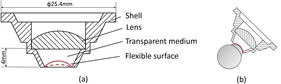
Figure 1 shows the schematic design of the probe. It is composed of a plano–covex lens and a cavity filled with transparent soft gel (such as agar). The probe has a rear diameter of 25.4 mm (1 in.), allowing it to be mounted on most of the off-the-shelf lens tubes. Due to the large difference in the ocular size between rats and mice, two sets of probes with very similar structure but different front diameters were made. According to rodent’s cornea size, the front diameters of the probe are 6 and 3 mm, corresponding to the corneal diameters of rats and mice, respectively[23].

Figure 1.Schematic design of the probe. (a) The structure of the contact probe for rats; (b) the surface of the soft gel can slightly change shape to adapt to different rodent eyes.
In this study, we chose agar as the filling gel in the cavity of the probe. The procedure steps are: (1) Deionized water, with a 0.5% concentration of agar, was heated to 90°C with continuous stirring; (2) after the agar was thoroughly dissolved and cooled to 40°C it was injected into the cavity; (3) a smooth steel ball, with a diameter similar to the rodent’s eye, was placed on the solution until the solution turned into gel state, as seen in Fig. 2. After removing the steel ball, there was a smooth concave surface that helps it to fit the cornea surface. The final gel is so soft that it can feasibly change the surface curvature to seamlessly cover the rodent’s cornea.
Figure 2.Making the concave surface with a steel ball.
To determine the parameters of the plano–convex lens and the thickness of the cavity, we performed a Zemax simulation. The optical parameters of the rat eye used in the simulation were based on references reported by Hughes[24], Campbell and Hughes[25], and Chaudhuri et al.[26], while parameters of the mouse eye were taken from Remtulla and Hallett[27] and Schmucker and Schaeffel[28]. The laser wavelength was 488 nm, and the illumination light entering the probe was collimated with a beam diameter of 3 and 2 mm for rats and mice, respectively. Therefore, this probe could be implemented in the clinical CSLO system, which images the human eye using collimated light. The beam diameters used were the maximum dilated pupil sizes for rats and mice[22]. The plano–concave-shaped agar gel (refractive index ) fills the space between the glass lens and cornea (), achieving index matching. Corneal refractive index matching has been used for the monochromatic measurement of crystalline lens aberrations[29,30], and also proved to improve current clinical retinal imaging techniques[31]. With refractive index matching, the main diopter is supplied by the anterior surface of the plano–convex lens. Via Zemax simulation, the selected lenses have a focal length of 12 mm and a diameter of 12 mm for rats, a focal length of 7.5 mm and a diameter of 6 mm for mice. The thicknesses of the cavity are 4 mm for rats and 2.75 mm for mice.
Figure 3 compared the performance in rat fundus imaging by the contact probe with a glass plano–concave lens used in the aforementioned second method. The plano–concave lens covering the cornea had a diameter and focal length . Another achromatic lens (, ) focuses the collimated light before the plano–concave lens to mimic a microscope. In Fig. 3, spot diagrams show that the diameter of the focal spot with our probe is 5.67 μm [Fig. 3(a)] versus 20 μm [Fig. 3(b)] for a plano–concave lens. The point spread function (PSF) comparison also indicated that the imaging quality with our contact probe [Fig. 3(c)] is better. Similar results were obtained for the mouse model.
Figure 3.Comparison between the flexible contact probe (a, c) and plano–concave method (b, d) in the spot diagram and PSF.
After performing the simulation study, we built the probe and tested its performance in a custom-made CSLO system, as seen in Fig. 4. The contact probe was fixed on the end of a 4-F lens tube (L5, L6). The light source was a 488 nm laser (OBIS 488LX, Coherent, Inc.). The beam diameter was expanded to 3 mm after the beam expander (L1, L2). The optical scanning system contains a resonant X scanner (CRS8, Cambridge Technology, Inc.) with 8 kHz oscillation frequency, and a galvanometer-based Y scanner (6210H, Cambridge Technology, Inc.). The adjustable collimating tube (L3, L4) can change the focal plane location by moving L3 to compensate the residual defocus. DM1 is a longpass dichroic mirror with a 505 nm cutoff wavelength, which reflects the 488 nm laser into the system and also allows other longer wavelength light sources to couple with the system. DM2 is a longpass dichroic mirror with a 500 nm cutoff wavelength for the fluorescence signal passing through. The avalanche photodiode is used to receive backscattered light from the retina, while the photomultiplier tube is adapted for weaker fluorescence light from either ecited fluorescein sodium or autofluorescence by lipofuscin, a kind of metabolic byproduct in the retina. The imaging frame rate was 15 Hz for this CSLO.
Figure 4.Layout of the CSLO system for rodents, and a photo of the contact probe with the subject. L: lens, DM: dichroic mirror, PBS: polarizing beam splitter, QWP: quarter wave plate.
Adult Sprague–Dawley (SD) rats (weight: 150 g) and BALB/c mice (weight: 20 g) were used in this study. The animal was first anesthetized by intraperitoneal injection of 4% chloral hydrate solution, and the animal’s pupil was dilated with one drop of a tropicamide compound consisting of 0.5% tropicamide and 0.5% phenylephrine. Then the artificial tears (Carbomer) were applied to the eye and the flexible contact probe was attached. It is noteworthy that, aided with the attached contact probe, eye movements were significantly reduced. All research complied with protocols approved by the Institutional Animal Care and Use Committee (IACUC) of Peking University.
We first compared the performance of this contact probe with the aforementioned second method in rat fundus imaging of the same rat eye. The plano–concave glass lens and achromatic lens to mimic the second method had the parameters stated in the simulation. The scanning area was approximately . All images in Fig. 5 except Fig. 5(c) were averaged over 30 frames. As seen in Figs. 5(a) and 5(b), the result using our contact probe [Fig. 5(a)] can achieve a better imaging quality over that from the plano–concave lens [Fig. 5(b)]. In addition, a bright speckle exists in reflectance images [Fig. 5(b)] that blocks images beneath, which is a common drawback of using glass contact lens.
Figure 5.In vivo retinal imaging. Comparison of the reflectance image by (a) the flexible contact probe and (b) the plano–concave lens for a rat; (c) autofluorescence imaging and (d) FA for the same rat; (e) reflectance and (d) fluorescence imaging for amouse. Scale bar: 100 μm.
After performance comparison, we performed fluorescence fundus imaging for both autofluorescence imaging (averaged over 100 frames because of the extremely weak signals) [Fig. 5(c)] and fluorescein angiography (FA) [Fig. 5(d)]. For FA, 150 μL 10% sodium fluorescein (Sigma-Aldrich, United States) was injected intraperitoneally. As seen in Fig. 5(d), the capillary network was clearly visualized.
Besides rat imaging, we continued to image the BALB/c mouse retina for reflectance [Fig. 5(e)] and FA (20 μL 10% sodium fluorescein) [Fig. 5(f)] using another contact probe designed for mice. The scanning area for mice was . Both reflectance and FA showed high-quality imaging results.
In conclusion, we present a contact probe for fundus imaging of rodents in CSLO. Both simulation and in vivo animal studies demonstrate that the probe can acquire high-quality fundus images for both rats and mice. The transparent agar gel adhering to the cornea can feasibly deform to fit various corneal surfaces. This is important because the corneal curvature and spherical refractive power of the SD rat eyes changes dramatically with age[22]. Also, the refractive index of the agar gel (approximately ) is closer to the cornea (e.g., rat, ) than that of glass (e.g., N-BK7, ) or air (), suppressing the wavefront error, as the error is linearly proportional to the refractive index difference[31]. In addition, the contact probe makes the optical alignment much easier, which significantly reduces the in vivo imaging time. However, the agar gel dehydrates quickly, and needs to be replaced frequently. In the future, we would like to explore other new materials. The electrical liquid lens could replace the plano–concave lens in Fig. 1(a) to achieve fast focusing. Finally, it is worthy to note that this contact probe also has great potential to be used on other ophthalmic optical devices, such as the optical coherence tomography, fundus camera, and therapy laser system for rodent models.
References
[1] Y. Shen, P. Zhuang, G. C. Chiou. Open Ophthalmol J., 5, 27(2011).
[2] B. Rohrer, Q. Long, B. Coughlin, R. B. Wilson, Y. Huang, F. Qiao, P. H. Tang, K. Kunchithapautham, G. S. Gilkeson, S. Tomlinson. Invest. Ophthalmol. Visual Sci., 50, 3056(2009).
[3] A. Matsubara, T. Nakazawa, K. Noda, H. She, E. Connolly, T. A. Young, Y. Ogura, E. S. Gragoudas, J. W. Miller. Age, 4741, 4747(2007).
[4] I. Obrosova, V. Drel, A. Kumagai, C. Szabo, P. Pacher, M. Stevens. Diabetologia, 49, 2525(2006).
[5] P. M. Martin, P. Roon, T. K. Van Ells, V. Ganapathy, S. B. Smith. Invest. Ophthalmol. Visual Sc.i, 45, 3330(2004).
[6] S. J. Reich, J. Fosnot, A. Kuroki, W. Tang, X. Yang, A. M. Maguire, J. Bennett, M. J. Tolentino. Mol. Vision, 9, 210(2003).
[7] H. Ye, Z. Gao, Z. Qin, Q. Wang. Chin. Opt. Lett., 11, 031702(2013).
[8] H. Ye, Z. Gao, T. Luo, Y. Huang. Chin. Opt. Lett., 8, 689(2010).
[9] G. Shi, Y. Dai, L. Wang, Z. Ding, X. Rao, Y. Zhang. Chin. Opt. Lett., 6, 424(2008).
[10] W. Wykes, A. Pyott, Y. Ferguson. Eye, 8, 437(1994).
[11] A. Manivannan, J. Kirkpatrick, P. Sharp, J. Forrester. Br. J. Ophthalmol., 78, 84(1994).
[12] M. W. Seeliger, S. C. Beck, N. Pereyra-Muñoz, S. Dangel, J.-Y. Tsai, U. F. O. Luhmann, S. A. van de Pavert, J. Wijnholds, M. Samardzija, A. Wenzel, E. Zrenner, K. Narfström, E. Fahl, N. Tanimoto, N. Acar, F. Tonagel. Vis. Res., 45, 3512(2005).
[13] R. H. Webb, G. W. Hughes. IEEE Trans. Biomed. Eng., BME-28, 488(1981).
[14] R. H. Webb. Appl. Opt., 23, 3680(1984).
[15] F. LaRocca, A.-H. Dhalla, M. P. Kelly, S. Farsiu, J. A. Izatt. J. Biomed. Opt., 18, 076015(2013).
[16] A. R. Rudnicka, R. O. W. Burk, D. F. Edgar, F. W. Fitzke. Ophthalmology, 105, 2186(1998).
[17] M. Kernt, U. C. Schaller, C. Stumpf, M. W. Ulbig, A. Kampik, A. S. Neubauer. Clin. Ophthalmol., 4, 829(2010).
[18] N. Eter. Molecular imaging in the eye Br. J. Ophthalmol., 94, 1420(2010).
[19] S. Wolf, O. Arend, W. E. Sponsel, K. Schulte, L. B. Cantor, M. Reim. Ophthalmology, 100, 1561(1993).
[20] C. J. Abbott, T. E. Choe, T. A. Lusardi, C. F. Burgoyne, L. Wang, B. Fortune. Biomed. Opt. Express, 4, 364(2013).
[21] S. Prilloff, J. Fan, P. Henrich-Noack, B. A. Sabel. Eu. J. Neurosci., 31, 521(2010).
[22] Y. Geng, K. P. Greenberg, R. Wolfe, D. C. Gray, J. J. Hunter, A. Dubra, J. G. Flannery, D. R. Williams, J. Porter. Invest. Ophthalmol. Visual Sci, 50, 5872(2009).
[23] G. Bawa, T. V. Tkatchenko, I. Avrutsky, A. V. Tkatchenko. Biomed. Opt. Express, 4, 2585(2013).
[24] A. Hughes. Vis. Res., 19, 569(1979).
[25] M. C. W. Campbell, A. Hughes. Vis. Res., 21, 1129(1981).
[26] A. Chaudhuri, P. E. Hallett, J. A. Parker. Vis. Res., 23, 1351(1983).
[27] S. Remtulla, P. E. Hallett. Vis. Res., 25, 21(1985).
[28] C. Schmucker, F. Schaeffel. Vis. Res., 44, 1857(2004).
[29] A. Dubinin, T. Cherezova, A. Belyakov, A. Kudryashov. J. Mod. Opt., 55, 671(2008).
[30] P. Artal, A. Guirao, E. Berrio, D. R. Williams. Compensation of corneal aberrations by the internal optics in the human eye, J. Vision, 1, 1(2001).
[31] N. Meitav, E. N. Ribak, A. V. Goncharov. Opt. Lett., 38, 745(2013).