Abstract
In this Letter, we propose that the photopatterned liquid crystal (LC) can act as a broadband and efficient terahertz (THz) Bessel vortex beam (BVB) generator. The mechanism lies in the frequency-independent geometric phase modulation induced by the spatially variant LC directors. By adopting large birefringence LCs and optimizing the cell gap, the maximized mode conversion efficiency can be continuously adjusted in broadband. Furthermore, the LC patterns can be designed and fabricated at will, which enables the THz BVBs to carry various topological charges. Such a THz LC BVB generator may facilitate the advanced THz imaging and communication apparatus.Terahertz (THz) waves are electromagnetic waves with an oscillation frequency of 0.1–10 THz. It is the least understood and developed band with distinguishing characteristics compared to the visible and microwave and contains great potential[1]. The THz wave exhibits lower photon energy compared to X ray, higher imaging resolution to ultrasonic, higher frequency to microwave, and strong penetration in many dielectric materials[2]. The above characteristics make THz technology attractive in wide fields including medical examination, remote sensing, and high-speed wireless communication[3,4]. The Bessel beam[5], a typical non-diffraction beam, shows the superiorities of excellent directivity, large focal depth, and low transmission loss; thus it is widely used in optical imaging, processing, and micro-manipulation[6,7]. The vortex beam is another specific electromagnetic field featured by a spiral phase distribution in the propagation section[8]. It brings a new dimension for optical manipulation, which could be quantitatively depicted by the topological charge, meaning how many twists the wave does in a single wavelength propagation. The vortex beam presents significant advantages in applications such as mode division communication and large-volume parallel quantum computing[9]. It is expected that the combination of above two beams may further upgrade advanced THz photonic devices.
During the past years, many techniques for specific THz beam generation have been developed, such as particularly designed phase plates, spatial light modulators, inhomogeneous birefringent crystals, and meta-devices[10–13]. By these means, specific THz beams including vortices, Airy beams, vector beams, and Bessel beams have been demonstrated[14–17]. However, present techniques are faced with several shortcomings. They suffer from either design and fabrication complexity or lack of function tunability and integration capability. Therefore, exploiting an efficient, tunable, and easy-to-integrate approach for THz specific beam generators is urgently demanded. Liquid crystals (LCs) possess broadband birefringence and excellent electro-optical tunability. Recently, both high-transparency electrodes and high-quality alignments have been settled for THz LC devices[18–20]. Especially, the photopatterned LCs are very suitable for manipulating the THz phase front in a geometric phase manner[21]. Meanwhile, the LC-based mode converters exhibit the following advantages: half-wave conditions (maximized mode conversion efficiency) can be electrically tuned in a broadband; the precise and free control of local optical axes enables the arbitrary wavefront manipulation.
In this Letter, a THz Bessel vortex beam (BVB) generator is proposed via integrating a spiral phase with a circular grating phase, and then the design is carried out by geometric phase modulation by means of a photopatterned LC. The non-diffraction propagation characteristics and the orbital angular momentum (OAM) mode on the transmission plane are numerically simulated. The performance of the THz BVB generator is characterized using a scanning near-field THz microscope (SNTM). The characteristics of the THz BVB generated by the LC geometric phase element are consistent with the simulations and exhibit high mode conversion efficiency in broadband.
Sign up for Chinese Optics Letters TOC. Get the latest issue of Chinese Optics Letters delivered right to you!Sign up now
Here, geometric phase, namely the Pancharatnam–Berry phase[22], is adopted for the design of the THz BVB generator. It originates from the photonic spin-orbit interaction and can be manipulated via the orientation control of anisotropic media, e.g., LCs and meta-resonators[23,24]. For a homogeneously aligned LC waveplate with orientation angle , its Jones matrix is where is the rotation matrix, is half of the phase retardation (, , and are LC birefringence, cell gap, and wavelength, respectively), and is the identity matrix. The normalized Jones vector is for left circular polarization (LCP) and for right circular polarization (RCP). When a circularly polarized wave is incident, the output wave is described as
For LCP incidence, the output wave is divided into two parts. One is the residual LCP component with no extra phase modulation. The other is the transformed RCP component with a phase factor and vice versa.
The designed phase diagram is composed of two parts: a vortex phase and a circular grating phase. The integrated phase satisfies the following equation:
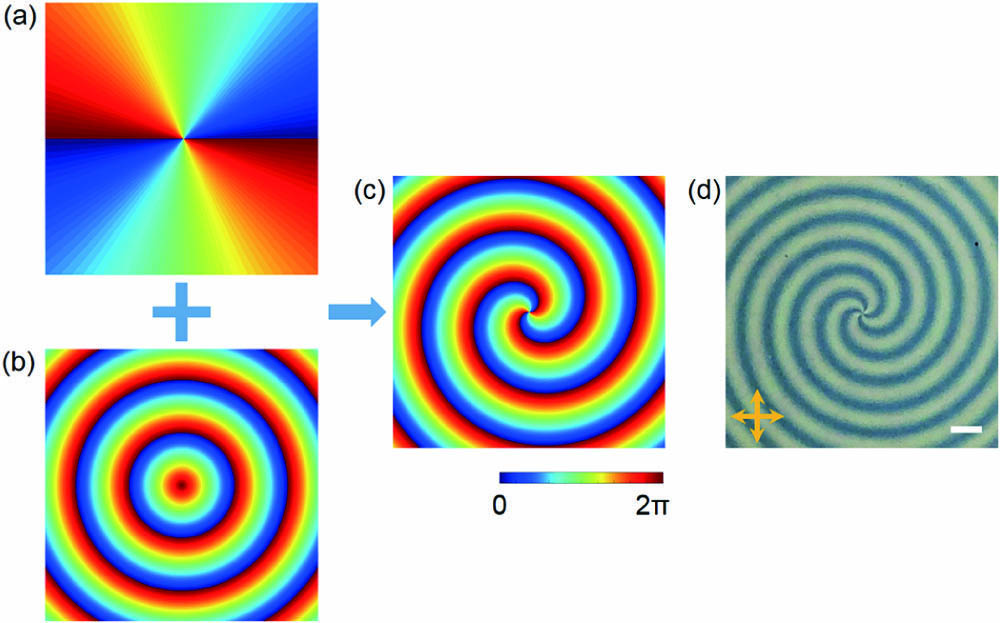
The first term on the right side denotes a vortex phase, where is the topological charge. The second term describes the introduced phase of a circular grating, where is the pitch of alternation along the radius . It acts as an axicon to generate a zeroth Bessel beam. The non-diffraction distance of the zeroth Bessel beam can be obtained by where is the radius of the axicon. As a proof of concept demonstration, we sum a vortex phase with [Fig. 1(a)] and a circular grating phase with [Fig. 1(b)]. The integrated phase is shown in Fig. 1(c). Apart from the phase diagram, the LC layer thickness, i.e., cell gap , is another important factor that determines the polarization conversion ratio (PCR). As illustrated in Eq. (2), PCR equals , that is, PCR is maximized only when satisfies the half-wave condition. Deviation from the half-wave condition will lead to a decrease of PCR. Here, is set as 400 μm to meet the half-wave condition at 1.2 THz.

Figure 1.Normalized phase diagrams of (a) a vortex plate with , (b) a circular grating with , and (c) their integration. (d) Photo of the fabricated LC sample under crossed polarizers (indicated by two orange arrows). Scale bar: 1 mm.
The fabrication process of such a THz LC BVB generator is illustrated as follows. Both substrates are 500-μm-thick fused silica. After being ultrasonically cleaned, the alignment layer sulfonic azo dye[25] (SD1, Dainippon Ink and Chemicals Inc., Chiba, Japan) is spin coated onto the substrates. Afterwards, the two substrates are assembled and separated by a 400-μm-thick Mylar to form a cell. A digital micro-mirror-device-based dynamic micro-lithography[26] is employed to control the local azimuthal angle of LC directors to obtain the desired phase diagram as exhibited in Fig. 1(c). After an LC NJU-LDn-4[27] with an average birefringence of 0.31 from 0.5 to 1.5 THz is infiltrated, the obtained LC orientation [Fig. 1(d)] agrees well with the design. It is noticed that the anchoring effect of our adopted azo dye alignment agent SD1 is very strong. In our test, the thick LC layer up to 500 μm can be well fabricated with little orientation defects. Also, the LC device works on the phase accumulation along the propagation. Even though the middle of the LC layer may not be aligned very well, it will not affect the THz performance of the device.
To verify the design, numerical simulations on the THz LC BVB generator are carried out using commercial simulation software Lumerical FDTD Solutions. The simulation is conducted based on the phase diagram shown in Fig. 1(c). A simulated model is established in the plane composed of many small LC pixels. Each pixel is set as . The LC is set as a diagonal dielectric material with (diagonal elements and ) and (diagonal element ). The LC director distributions are set by an LC orientation module. A plane THz wave is incident along the axis. Figure 2(a) reveals the simulated THz intensity distribution in the plane of an LCP wave at 1.2 THz, which shows a THz far field with a non-diffraction distance of more than 20 mm. The central dark region corresponds to the singularity of the vortex beam. The donut-like intensity distributions are observed in the plane [Figs. 2(b) and 2(c)]. The concentric rings with exponentially decreased intensity around the central one are attributed to the far field diffraction. The diameters of the central ring at and that at are almost the same, verifying the non-diffraction property of the BVB. The simulated phase distributions at 1.2 THz in the planes are also shown. Two alternations in the center indicate an OAM with .
Figure 2.(a) Simulated normalized THz intensity distribution in the plane at 1.2 THz. The white dashed lines indicate and 20 mm. Simulated THz intensity and phase distributions at 1.2 THz in the plane at (b) and (c) , respectively.
An SNTM setup[28] (Terahertz Photonics Co., Ltd., China), working on the photoconductive THz generation and detection, is utilized to characterize the performance of the BVB generator. In this setup, a scanning tip fixed on a motorized stage is utilized to record the field in the plane with a step size of 0.2 mm. The sample moves along the axis with a step size of 0.5 mm to capture the field in the plane. The measured THz intensity distributions in the plane at 1.2 THz are shown in Fig. 3(a). Figures 3(b)–3(e) are the measured THz intensity and phase distributions at 1.2 THz in the plane at , 10 mm, 15 mm, and 20 mm in subsequence. The featured donut-like intensity profiles and the vortex phase are clearly presented. Though the diameter of the central ring gradually increases, the result matches well with the simulation, indicating non-diffraction. To quantitatively evaluate the beam profile in the transmission section, the intensity along the and axes in Fig. 3(b) is plotted in Fig. 3(f). Each one shows a dip at and two peaks aside. The exponentially decreased side lobes can also be observed in transmission sections. All of the spin-converted waves carry the designed phase; therefore, the mode conversion efficiency is determined by the PCR. The dependency of PCR on frequency is calculated and plotted in Fig. 3(g). The nearly unit PCR at 1.2 THz is due to an optimized half-wave condition.
Figure 3.(a) Measured THz intensity distributions in the plane at 1.2 THz. The white dashed lines indicate , 10, 15, and 20 mm, separately. (b)–(e) Measured THz intensity and phase distributions at 1.2 THz in the -plane at (b) , (c) , (d) , and (e) , respectively. (f) Normalized intensity profiles along the and axes labeled by the dashed lines in (b). (g) Dependency of PCR on frequency.
Thanks to the frequency-independent geometric phase modulation, the LC BVB generator works in broadband. We characterize its performance at 1.1 and 1.4 THz, which is shown in Fig. 4. The intensity distributions in the plane [Figs. 4(a) and 4(b)] indicate a well-preserved non-diffraction property of the BVB. Both intensity and phase distributions in the plane are quite similar to that at 1.2 THz, verifying its capability in broadband THz wave manipulations.
Figure 4.Measured THz intensity distributions in the plane at (a) 1.1 THz and (b) 1.4 THz. The white dashed lines in (a) and (b) indicate . THz intensity and phase distributions in the plane at (c) 1.1 THz and (d) 1.4 THz.
The THz LC devices possess an LC layer thickness (hundreds of microns) far beyond those in the visible due to their longer wavelength. To reduce the thickness to some extent, LC birefringence should be large enough to achieve the full phase accumulation of . In our experiments, NJU-LDn-4 with a large birefringence of 0.31 from 0.5 to 1.5 THz is adopted. In this case, the 400-μm-thick LC layer is required to meet the half-wave condition at 1.2 THz, which can be well oriented by the azo dye alignment agent SD1 with a large anchoring energy[29]. The elastic constant mainly affects the switching performance of the LC device. As we did not demonstrate electrical tuning, the elastic constant of the LC is not considered.
The proposed THz LC BVB generator works on the geometric phase modulation of a specifically designed inhomogeneous waveplate. The phase diagram is the integration of a vortex plate and a circular grating. With this plate, the generated BVB exhibits characteristics of both vortex and Bessel beams. The BVB carries topological property depicted by OAM and significant non-diffraction induced good directivity. These unique properties make the BVB an excellent candidate for detections, micro-manipulations, and mode-division-multiplexing-based communications. The geometric phase mechanism and broadband birefringence of LCs make the fabricated BVB generator applicable in broadband. Moreover, the half-wave condition determined maximum mode conversion efficiency, combined with the external field induced tunability of LCs, makes tunable or even switchable mode converters available. Due to the high resolution of the director distribution control and pronounced flexibility of wavefront manipulation, various mode encoding can be reasonably expected. Further integrating such geometric phase LC elements with meta-devices[30,31] will significantly extend the functions of THz elements, making even active dispersion manipulation and spin-multiplexed THz photonics achievable.
In conclusion, we propose and demonstrate a THz BVB generator based on the geometric phase modulation of a specially designed inhomogeneous LC waveplate that combines a spiral phase and a circular grating phase. The generated BVB carries a topological charge and exhibits excellent directivity. These characteristics make it suitable for advanced THz applications. Its broadband operation capability is demonstrated, and electrically tuned efficiency can be expected. The proposed elements can be further integrated with meta-devices, which may upgrade the exsiting THz apparatues.
References
[1] B. Ferguson, X. C. Zhang. Nat. Mater., 1, 26(2002).
[2] X. C. Zhang, J. Xu. Introduction to THz Wave Photonics, 29(2010).
[3] S. Koenig, D. Lopez-Diaz, J. Antes, F. Boes, R. Henneberger, A. Leuther, A. Tessmann, R. Schmogrow, D. Hillerkuss, R. Palmer, T. Zwick, C. Koos, W. Freude, O. Ambacher, J. Leuthold, I. Kallfass. Nat. Photon., 7, 977(2013).
[4] K. Kawase, Y. Ogawa, Y. Watanabe, H. Inoue. Opt. Express, 11, 2549(2003).
[5] D. McGloin, K. Dholakia. Contemporary Phys., 46, 15(2005).
[6] J. Zheng, Y. Yang, M. Lei, B. Yao, T. Ye. Appl. Opt., 51, 7236(2012).
[7] M. K. Bhuyan, F. Courvoisier, P. A. Lacourt, M. Jacquot, J. M. Dudley. Opt. Express, 18, 566(2010).
[8] A. O’neil, I. MacVicar, L. Allen, M. Padgett. Phys. Rev. Lett., 88, 053601(2002).
[9] J. Wang, J. Y. Yang, I. M. Fazal, N. Ahmed, Y. Yan, H. Huang, Y. Ren, Y. Yue, S. Dolinar, M. Tur. Nat. Photonics, 6, 488(2012).
[10] K. Miyamoto, K. Suizu, T. Akiba, T. Omatsu. Appl. Phys. Lett., 104, 261104(2014).
[11] W. L. Chan, H. T. Chen, A. J. Taylor, I. Brener, M. J. Cich, D. M. Mittleman. Appl. Phys. Lett., 94, 213511(2009).
[12] A. Minasyan, C. Trovato, J. Degert, E. Freysz, E. Brasselet, E. Abraham. Opt. Lett., 42, 41(2017).
[13] D. Hu, X. Wang, S. Feng, J. Ye, W. Sun, Q. Kan, P. J. Klar, Y. Zhang. Adv. Opt. Mater., 1, 186(2013).
[14] S. J. Ge, P. Chen, Z. X. Shen, W. F. Sun, X. K. Wang, W. Hu, Y. Zhang, Y. Q. Lu. Opt. Express, 25, 12349(2017).
[15] C. Liu, L. Niu, K. Wang, J. Liu. Opt. Express, 24, 29342(2016).
[16] R. Imai, N. Kanda, T. Higuchi, Z. Zheng, K. Konishi, M. Kuwata-Gonokami. Opt. Express, 20, 21896(2012).
[17] S. Liu, A. Noor, L. L. Du, L. Zhang, Q. Xu, K. Luan, T. Q. Wang, Z. Tian, W. X. Tang, J. G. Han. ACS Photon., 3, 1968(2016).
[18] L. Wang, X. W. Lin, W. Hu, G. H. Shao, P. Chen, L. J. Liang, B. B. Jin, P. H. Wu, H. Qian, Y. N. Lu, X. Liang, Z. G. Zheng, Y. Q. Lu. Light Sci. Appl., 4, e253(2015).
[19] C. S. Yang, T. T. Tang, P. H. Chen, R. P. Pan, P. Yu, C. L. Pan. Opt. Lett., 39, 2511(2014).
[20] Y. Du, H. Tian, X. Cui, H. Wang, Z. X. Zhou. J. Mater. Chem. C, 4, 4138(2016).
[21] Z. X. Shen, S. H. Zhou, S. J. Ge, W. Duan, L. L. Ma, Y. Q. Lu, W. Hu. Opt. Express, 27, 8800(2019).
[22] M. V. Berry. J. Modern Opt., 34, 1401(1987).
[23] P. Chen, L. L. Ma, W. Hu, Z. X. Shen, H. K. Bisoyi, S. B. Wu, S. J. Ge, Q. Li, Y. Q. Lu. Nat. Commun, 10, 2518(2019).
[24] G. Zheng, H. Mühlenbernd, M. Kenney, G. Li, T. Zentgraf, S. Zhang. Nat. Nanotechnol., 10, 308(2015).
[25] Z. X. Shen, M. J. Tang, P. Chen, S. H. Zhou, S. J. Ge, W. Duan, T. Wei, X. Liang, W. Hu, Y. Q. Lu. Adv. Opt. Mater., 8, 1902124(2020).
[26] P. Chen, S. J. Ge, W. Duan, B. Y. Wei, G. X. Cui, W. Hu, Y. Q. Lu. ACS Photon., 4, 1333(2017).
[27] L. Wang, X. W. Lin, X. Liang, J. B. Wu, W. Hu, Z. G. Zheng, B. B. Jin, Y. Q. Qin, Y. Q. Lu. Opt. Mater. Express, 2, 1314(2012).
[28] Z. X. Shen, S. H. Zhou, X. A. Li, S. J. Ge, P. Chen, W. Hu, Y. Q. Lu. Adv. Photon., 2, 036002(2020).
[29] V. G. Chigrinov, V. M. Kozenkov, H. S. Kwok. Photoalignment of Liquid Crystalline Materials: Physics and Applications(2008).
[30] Z. X. Shen, S. H. Zhou, S. J. Ge, W. Duan, P. Chen, L. Wang, W. Hu, Y. Q. Lu. Opt. Lett., 43, 4695(2018).
[31] Z. X. Shen, S. H. Zhou, S. J. Ge, W. Hu, Y. Q. Lu. Appl. Phys. Lett., 114, 041106(2019).