• Photonics Research
  • Vol. 10, Issue 11, 2541 (2022)
Song Qiu1、2, Xiangyang Zhu1、2, Ruoyu Tang1、2, Tong Liu1、2, Ruijian Li1、2, and Yuan Ren2、3、*
Author Affiliations
  • 1Department of Aerospace Science and Technology, Space Engineering University, Beijing 101416, China
  • 2Lab of Quantum Detection & Awareness, Space Engineering University, Beijing 101416, China
  • 3Department of Basic Course, Space Engineering University, Beijing 101416, China
  • show less
    DOI: 10.1364/PRJ.461039 Cite this Article Set citation alerts
    Song Qiu, Xiangyang Zhu, Ruoyu Tang, Tong Liu, Ruijian Li, Yuan Ren. Noncoaxial RDE of circular asymmetry optical vortex for rotating axis detection[J]. Photonics Research, 2022, 10(11): 2541 Copy Citation Text show less
    Schematic of the coaxial and noncoaxial RDE. (a) A tiny scatterer from a rotating body is taken out to analyze the relationship between the Poynting vector and the scatterer velocity on the condition of coaxial incidence. pϑ→ and pz→ are the angular and the propagation component, respectively. (b) The misaligned detection condition under the rotating center completely derivates out of the OV ring. Relative to the CS established with the spot center as the origin, the position of the small scatterer is defined by θ and r→, and the position of the rotating center is defined by γ and d→. The RDE frequency shift is introduced through the velocity component of the scatterer in the tangent direction.
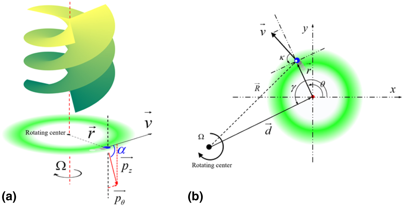
    Fig. 1. Schematic of the coaxial and noncoaxial RDE. (a) A tiny scatterer from a rotating body is taken out to analyze the relationship between the Poynting vector and the scatterer velocity on the condition of coaxial incidence. pϑ and pz are the angular and the propagation component, respectively. (b) The misaligned detection condition under the rotating center completely derivates out of the OV ring. Relative to the CS established with the spot center as the origin, the position of the small scatterer is defined by θ and r, and the position of the rotating center is defined by γ and d. The RDE frequency shift is introduced through the velocity component of the scatterer in the tangent direction.
    Simulated results of the RDE frequency shifts generated by the four parts A, B, C, and D of the OV, where the horizontal direction expresses the orientation of the rotating axis, and the vertical direction denotes the RDE frequency shift. It is clear that when the rotating axis is in the different quadrants of the CS, the magnitudes of the frequency shift caused by the four parts are different.
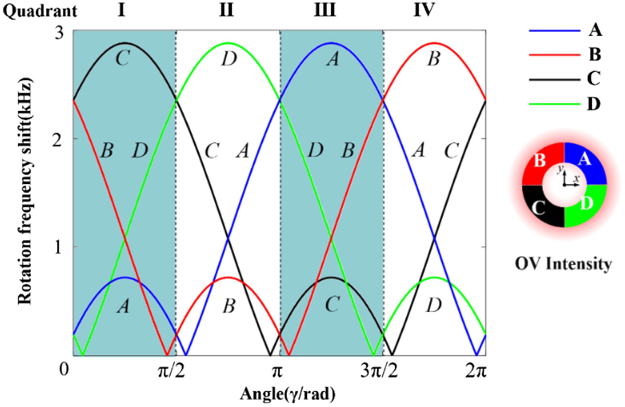
    Fig. 2. Simulated results of the RDE frequency shifts generated by the four parts A, B, C, and D of the OV, where the horizontal direction expresses the orientation of the rotating axis, and the vertical direction denotes the RDE frequency shift. It is clear that when the rotating axis is in the different quadrants of the CS, the magnitudes of the frequency shift caused by the four parts are different.
    Experimental setup. The laser source generates the laser with wavelength of 532 nm. Ex, beam expander; SLM, spatial light modulator; L, lens; Ap, aperture; BS, beam splitter; APD, avalanche photodetector. The holograms uploaded on the SLM are shown in the left of the diagram. DAC is the data acquisition card. A computer plays the role of the control center, which can adjust the hologram on the SLM and the rotation of the rotor, as well as its position change along the x and y directions.
    Fig. 3. Experimental setup. The laser source generates the laser with wavelength of 532 nm. Ex, beam expander; SLM, spatial light modulator; L, lens; Ap, aperture; BS, beam splitter; APD, avalanche photodetector. The holograms uploaded on the SLM are shown in the left of the diagram. DAC is the data acquisition card. A computer plays the role of the control center, which can adjust the hologram on the SLM and the rotation of the rotor, as well as its position change along the x and y directions.
    Experimentally observed RDE under illumination of a quarter of light field. (a)–(d) The four partial circular asymmetry OV fields relative to the rotating center; (e)–(h) the corresponding RDE frequency shift introduced by the four parts.
    Fig. 4. Experimentally observed RDE under illumination of a quarter of light field. (a)–(d) The four partial circular asymmetry OV fields relative to the rotating center; (e)–(h) the corresponding RDE frequency shift introduced by the four parts.
    (a)–(d) Experiment results under the illumination of the rotating center on one axis of the spot center-based CS. It is clear that the frequency shift generated by OV fields B and C is the same and smaller than the frequency shift generated by A and D. (e) Measurement results in eight orientations in the CS. By comparing the frequency shift introduced by the four parts, the orientation of the rotating axis relative to the OV center can be obtained according to the theoretical principle.
    Fig. 5. (a)–(d) Experiment results under the illumination of the rotating center on one axis of the spot center-based CS. It is clear that the frequency shift generated by OV fields B and C is the same and smaller than the frequency shift generated by A and D. (e) Measurement results in eight orientations in the CS. By comparing the frequency shift introduced by the four parts, the orientation of the rotating axis relative to the OV center can be obtained according to the theoretical principle.
    Energy flow of the single and superposed mode incomplete OV. (a) and (c) are the light field in the initial plane. (b) and (d) are the light field after the propagation distance of 4 m. It can be seen that the superposed OV is affected less significantly than the single mode by the energy flow.
    Fig. 6. Energy flow of the single and superposed mode incomplete OV. (a) and (c) are the light field in the initial plane. (b) and (d) are the light field after the propagation distance of 4 m. It can be seen that the superposed OV is affected less significantly than the single mode by the energy flow.
    Data processing process. (a) Echo data in the time domain; (b) signals in the frequency domain; (c) result after the notch filter, which can eliminate the circuit noise frequency of 120 Hz and its harmonics; (d) frequency peak after the smooth filter with step size of 100.
    Fig. 7. Data processing process. (a) Echo data in the time domain; (b) signals in the frequency domain; (c) result after the notch filter, which can eliminate the circuit noise frequency of 120 Hz and its harmonics; (d) frequency peak after the smooth filter with step size of 100.
    Song Qiu, Xiangyang Zhu, Ruoyu Tang, Tong Liu, Ruijian Li, Yuan Ren. Noncoaxial RDE of circular asymmetry optical vortex for rotating axis detection[J]. Photonics Research, 2022, 10(11): 2541
    Download Citation