• High Power Laser and Particle Beams
  • Vol. 32, Issue 11, 112002 (2020)
Feng Wang, Xing Zhang, Yulong Li, Bolun Chen, Zhongjing Chen, Tao Xu, Xincheng Liu, Hang Zhao, Kuan Ren, Jiamin Yang, Shaoen Jiang, and Baohan Zhang
Author Affiliations
  • Laser Fusion Research Center, CAEP, P. O. Box 919-988, Mianyang 621900, China
  • show less
    DOI: 10.11884/HPLPB202032.200136 Cite this Article
    Feng Wang, Xing Zhang, Yulong Li, Bolun Chen, Zhongjing Chen, Tao Xu, Xincheng Liu, Hang Zhao, Kuan Ren, Jiamin Yang, Shaoen Jiang, Baohan Zhang. Progress in high time- and space-resolving diagnostic technique for laser-driven inertial confinement fusion[J]. High Power Laser and Particle Beams, 2020, 32(11): 112002 Copy Citation Text show less
    Schematic diagram of all-optical diagnostic technology for single point pulse behavior measurement
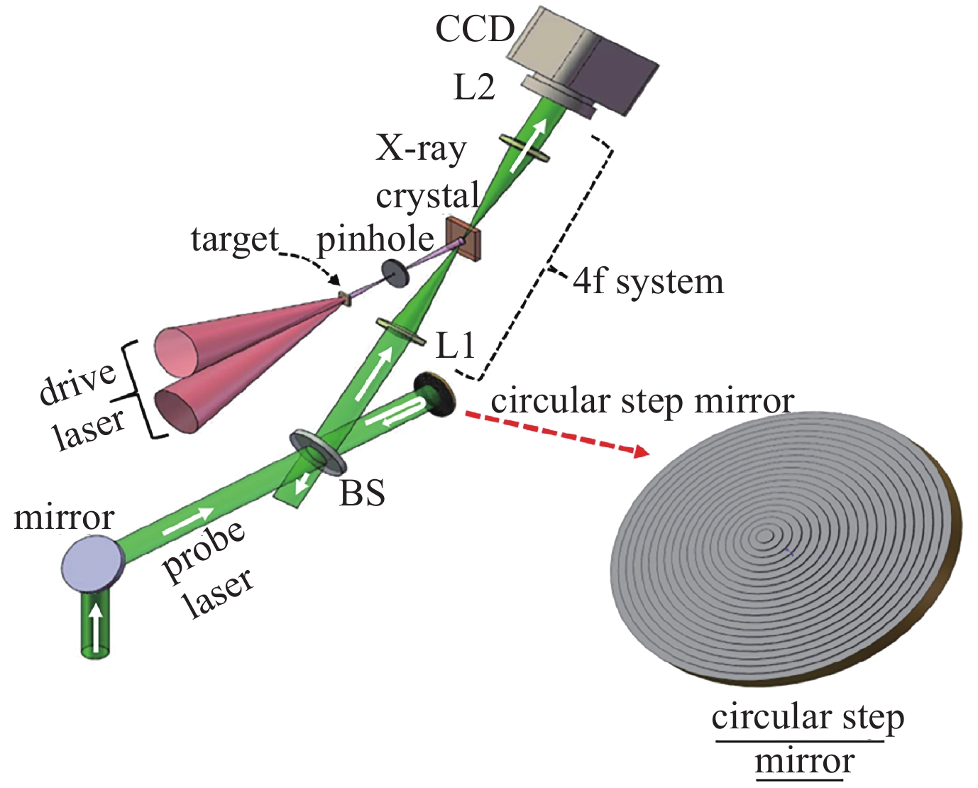
    Fig. 1. Schematic diagram of all-optical diagnostic technology for single point pulse behavior measurement
    Typical measurement results of single pulse transient behavior
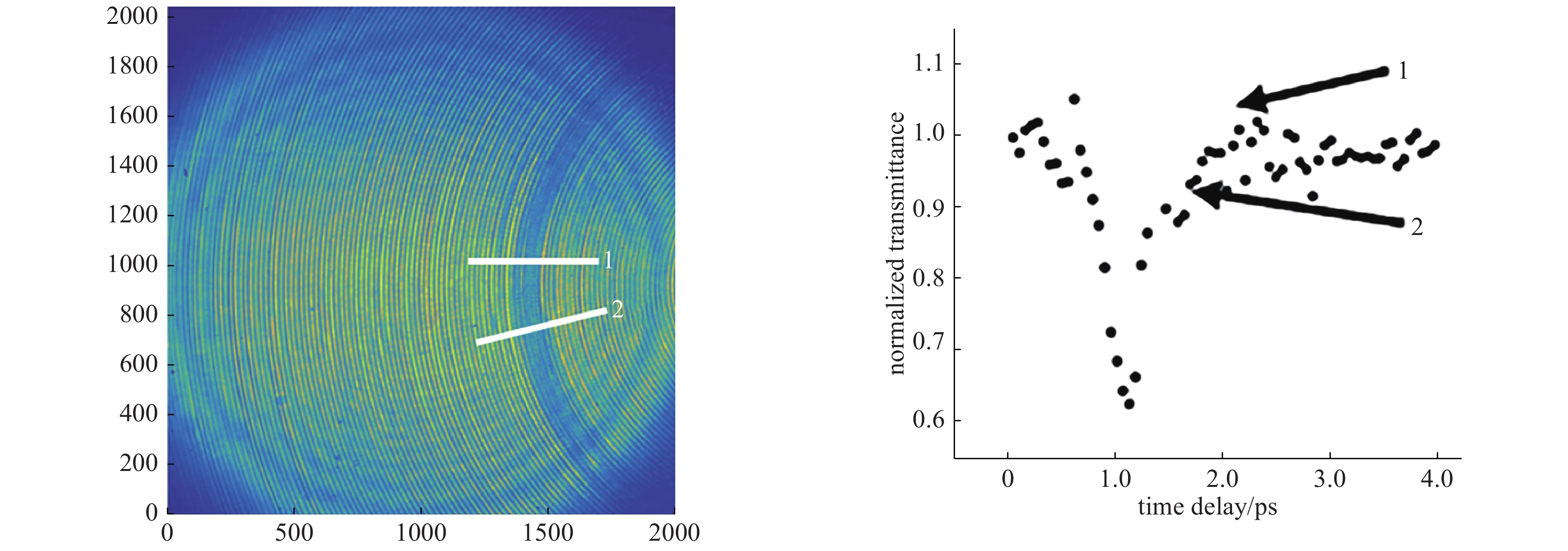
    Fig. 2. Typical measurement results of single pulse transient behavior
    Optical path diagram of high time-resolving all optical scanning diagnostic technology based on photorefractive effect
    Fig. 3. Optical path diagram of high time-resolving all optical scanning diagnostic technology based on photorefractive effect
    Schematic diagram of all-optical framing imaging diagnostic technique
    Fig. 4. Schematic diagram of all-optical framing imaging diagnostic technique
    Time response data of all-optical frame imaging diagnostic converter
    Fig. 5. Time response data of all-optical frame imaging diagnostic converter
    Optic design of the reflective KB microscope
    Fig. 6. Optic design of the reflective KB microscope
    (a) Energy responses of the KB microscope and (b) the reflectivity spatial distribution of 6 keV X-ray
    Fig. 7. (a) Energy responses of the KB microscope and (b) the reflectivity spatial distribution of 6 keV X-ray
    Backlit image of the four-phase mesh and the analysis of the spatial resolution of full reflection KB imaging system
    Fig. 8. Backlit image of the four-phase mesh and the analysis of the spatial resolution of full reflection KB imaging system
    Measured hot spot images in the exploding pusher target and the indirectly driven implosions
    Fig. 9. Measured hot spot images in the exploding pusher target and the indirectly driven implosions
    Optics design of the multi-layer coated quasi-monenergistic response KB microscope
    Fig. 10. Optics design of the multi-layer coated quasi-monenergistic response KB microscope
    Throughout response of the multi-layer coated KB microscope (a) and the backlit image of an 1000# Ni mesh (b) and the hot spot image in the hohlraum driven implosion (c)
    Fig. 11. Throughout response of the multi-layer coated KB microscope (a) and the backlit image of an 1000# Ni mesh (b) and the hot spot image in the hohlraum driven implosion (c)
    Schematic diagram of imaging principle for each imaging dimension of KBA micro imaging system
    Fig. 12. Schematic diagram of imaging principle for each imaging dimension of KBA micro imaging system
    (a)structural diagram of dual channel KBA-KB imaging system;(b)the backlit image of a 600# Au mesh
    Fig. 13. (a)structural diagram of dual channel KBA-KB imaging system;(b)the backlit image of a 600# Au mesh
    (a) Structural diagram of the AKB imaging system;(b) optics diagram of the AKB imaging in sagittal and tangential directions
    Fig. 14. (a) Structural diagram of the AKB imaging system;(b) optics diagram of the AKB imaging in sagittal and tangential directions
    (a) Spherically bent crystal samples fabricated by LFRC and (b) the test result at laser facility
    Fig. 15. (a) Spherically bent crystal samples fabricated by LFRC and (b) the test result at laser facility
    Diagram of the monochromatic imaging system with spherical crystal installed on the DIM
    Fig. 16. Diagram of the monochromatic imaging system with spherical crystal installed on the DIM
    2D radiography applications of the monochromatic imaging system with spherical crystal
    Fig. 17. 2D radiography applications of the monochromatic imaging system with spherical crystal
    Implosion trajectory measurement image by the monochromatic imaging system with spherical crystal
    Fig. 18. Implosion trajectory measurement image by the monochromatic imaging system with spherical crystal
    (a)Single line-of-sight (SLOS) X-ray imager and(b) schematic diagram of photoelectron expanding principle
    Fig. 19. (a)Single line-of-sight (SLOS) X-ray imager and(b) schematic diagram of photoelectron expanding principle
    (a)Schematic diagram of four end fed cathode structure and(b)four channel composite waveforms
    Fig. 20. (a)Schematic diagram of four end fed cathode structure and(b)four channel composite waveforms
    (a)Photo of drift tube of double lens short magnetic focusing lens and(b)image of adjusting the current of two magnetic lenses to obtain 10 lp/mm resolution
    Fig. 21. (a)Photo of drift tube of double lens short magnetic focusing lens and(b)image of adjusting the current of two magnetic lenses to obtain 10 lp/mm resolution
    Geometric model for neutron penumbral imaging
    Fig. 22. Geometric model for neutron penumbral imaging
    Designed biconic-shaped geometric aperture parameters and the spatial resolution contributed by the aperture
    Fig. 23. Designed biconic-shaped geometric aperture parameters and the spatial resolution contributed by the aperture
    Measured line-spread function of the neutron image detector
    Fig. 24. Measured line-spread function of the neutron image detector
    Principle of the light field camera
    Fig. 25. Principle of the light field camera
    diagnostic equipmentradiationtemporal resolution/ps1D/2Dframe
      Note:1)The product introduction currently available for fs streak camera comes from Hamamatsu Photonics. As the product needs to be triggered by fs pulses, it has not been applied in ICF researches internationally and domestically. ;2)The Sequentially Timed All Optical Mapping Photography (STAMP) technology, as a quite new idea, can help and learn from the overall technical system of ICF. However, it is oriented to basic and laboratory research, not fit for large ICF facilities.
    Multi-MCPoptical/X-ray50~802D,33 μm~16
    DIXIX-ray102D,100 μm~16
    Streak Camera1)optical/X-ray0.51D,50 μm——
    CUPoptical/X-ray22D,100 μm20−30 or more
    STAMP2)optical~0.12D,10 μm>6
    Table 1.

    Common techniques for high temporal resolution purposes

    国际上常见的高时间分辨的几个技术状态比较

    reflectorcurvature radius/mmagnificationgrazing incidence angle/(°)mirror length/mmobject distance/mmimage distance/mm
    horizontal50210.437 5122004200
    vertical5019.80.452 5122124188
    Table 2.

    Parameters of the reflective KB microscope

    反射式宽能带KB显微成像系统光学参数

    reflectorcurvature radius/mmagnificationgrazing incidence angle/(°)mirror lenght/mmobject distance/mmimage distance/mm
    P119.5201.175 4102104200
    P221.019.0451.140 7102204190
    P319.518.1741.281 21023041801
    Table 3.

    Parameters of the multi-layer coated quasi-monenergistic response KB microscope

    多层膜单能响应KB显微成像系统光学参数

    Feng Wang, Xing Zhang, Yulong Li, Bolun Chen, Zhongjing Chen, Tao Xu, Xincheng Liu, Hang Zhao, Kuan Ren, Jiamin Yang, Shaoen Jiang, Baohan Zhang. Progress in high time- and space-resolving diagnostic technique for laser-driven inertial confinement fusion[J]. High Power Laser and Particle Beams, 2020, 32(11): 112002
    Download Citation