
Mauro Temporal, Benoit Canaud, Warren J. Garbett, Rafael Ramis, and Stefan Weber, "Irradiation uniformity at the Laser MegaJoule facility in the context of the shock ignition scheme," High Power Laser Sci. Eng. 2, 020000e8 (2014)
- High Power Laser Science and Engineering
- Vol. 2, Issue 2, 020000e8 (2014)
Abstract
1. Introduction
One of the main goals of inertial confinement fusion (ICF)[ MeV – throughout the compressed fuel should generate a large energy gain
  (ratio between thermonuclear fusion and the invested energy). To this aim two schemes have been proposed, namely: direct drive and indirect drive. In both cases a spherical capsule containing the DT nuclear fuel is considered. In the direct drive[
 casing; see
  ) before stagnating to produce a high-density (hundreds of
  ) shell that confines a fraction of the DT fuel (hundreds of
  ). The ignition conditions require that the central mass, called the hot-spot, is heated to high temperature (10 keV) and confined into a volume with an areal density comparable with the
  -particle range (
 ).
).
A crucial issue concerns the uniformity of the capsule irradiation. A successful capsule implosion requires a very uniform irradiation and capsule target; otherwise, the imploding shell suffers the growth of dangerous hydrodynamic instabilities (Richtmyer–Meshkov[ . This causes a detriment of the energy gain
  which scales[
 , where
  is the fractional burn-up[
 the fuel areal density, and
  the incident laser intensity.
Alternative schemes are currently under study, such as fast ignition induced by laser accelerated electrons[ and does not allow for the generation of an efficient hot-spot. In the SI scheme, a second high-power (hundreds of TW) laser pulse irradiates the capsule and drives a strong shock wave that reaches the compressed shell providing the fuel ignition. The SI pulse must be carefully tuned in time to synchronize the strong shock wave with the compression shock rebounded from the centre after stagnation. This new scheme promises higher gain[
 [
[ 10–40 keV) electrons[
Sign up for High Power Laser Science and Engineering TOC. Get the latest issue of High Power Laser Science and Engineering delivered right to you!Sign up now
Due to its indirect drive design, the LMJ facility does not provide a favourable laser beam configuration for direct drive irradiation. Nevertheless, this large facility is very attractive for direct drive studies because of its large available energy. In this context, this paper aims to chart a path starting from the current characteristics of the LMJ facility and exploring the potential of the shock ignition scheme. After summarizing the main characteristics of the LMJ facility in Section
2. The Laser MegaJoule configuration
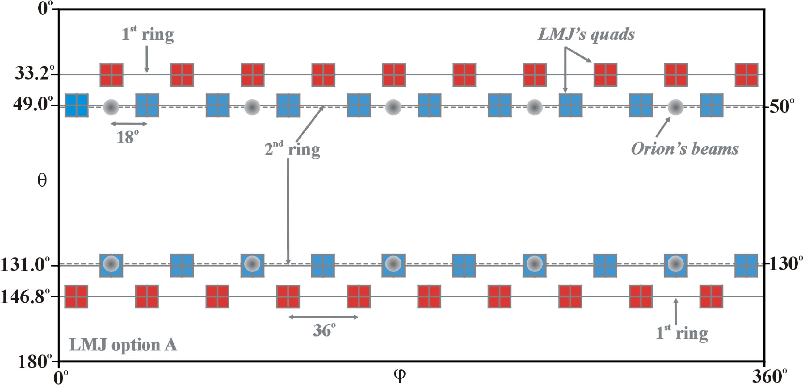
The configuration of the Laser MegaJoule facility considered in this paper consists of 176 high-power laser beams. These beams are grouped in 44 identical quads, each one composed by four beams. 40 quads are distributed into the spherical experimental chamber in four axial symmetric rings, and the two hemispheres are rotated by  . The two rings closer to the polar axis have an angle of
  and
and  with each having 10 quads; another 20 quads are located in the rings at
  and
and  , as shown in Figure
  and
and  . The LMJ architecture is designed to provide a maximum laser energy (power) of 7.5 kJ (2.5 TW) for each beam. Consequently, this corresponds to a total energy (power) of 30 kJ (10 TW) per quad, and each pair of rings will provide a maximum energy (power) of 600 kJ (200 TW). This makes the LMJ a large laser facility, able to drive a total energy of about 1.3 MJ with a maximum power of 440 TW delivered by laser beams with a wavelength of
  (
( )[
)[
The polar coordinates of the quads have been optimized for the indirect drive scheme. Nevertheless, this laser beam distribution could be helpful also in the direct drive shock ignition scheme. Indeed, as already mentioned, this scheme involves two laser pulses: one for the capsule compression and a second one for the fuel ignition. Thus, there are several options in order to use the LMJ facility as a direct drive facility in the context of the SI scheme. Hereafter, we will consider two options: option A, where 20 quads of the second ring are devoted to the compression of the capsule and with the other 24 quads driving the high-power shock ignition pulse; and option B, with only 10 quads of the second ring devoted to the foot pulse while together with the remaining 34 quads contributing to the drive and the igniting pulse. The main difference between the two options concerns the role of the different quads in the partition of laser power during the low-power foot pulse, the main drive of the compression phase, and the shock ignition phase.
Of course, the choice of the irradiation configuration also has consequences on the irradiation uniformity. Details of these configurations are given in the temporal power pulse sketched in Figure
The division of tasks among the different quads also allows implementing in a natural way both the polar direct drive (PDD)[
It is worth noting that the Orion facility in the UK is composed of 12 beams: two laser beams provide 500 J each at  (1054 nm) in a short pulse of 0.5 ps and the other ten provide a total energy of 5 kJ (
 ,
,  nm) in 1–5 ns long pulses. The angular positions of these ten beams are indicated by gray circles in Figure
  beams are located in two rings at
  and
and  with respect to the polar angle. This beam distribution is very similar to the one provided by the second ring of the LMJ facility. This makes the Orion facility the natural choice to test relevant aspects inherent to the LMJ facility such as the laser absorption and the improvement of the irradiation uniformity promised by the PDD technique. Indeed, despite the relatively small dimensions, 5 kJ in 5 ns for 1 TW, this facility is perfectly matched to the requirements of experiments dedicated to the study of the imprint phase, where the first shock wave is driven by a low-power (
 TW) foot pulse.
3. Shock ignition calculations
A relatively large direct drive capsule characterized by an initial aspect ratio  has been considered. This capsule is part of a family of capsules that have been recently studied[
 and contains a DT fuel mass of
  g. The cryogenic nuclear fuel
  is surrounded by a thin (
 ) shell of plastic (
 devoted to the laser energy absorption. Detailed parametric studies have been performed showing that the self-ignition threshold in the implosion velocity is about
  [
[ with an incident energy of about 500 kJ and laser peak power of 230 TW[
Here, the capsule has been used in the context of the shock ignition scheme, and a series of 1D numerical calculations has been performed with the hydro-radiative MULTI code[ – the intensity is reduced to
  at the initial capsule radius – has been considered. The laser pulse is composed of a low-power foot pulse (
 ns at
ns at  TW) followed by the main pulse with a maximum power
  TW (see the shadow area in Figure
  and the power grows linearly, reaching the maximum power
  in 100 ps; the maximum power holds for 300 ps and then goes down to zero in another 100 ps.
In Figure  ns, where the shock ignition pulse began. The maximum incident laser power during the compression phase is
  TW, which then grows to
  TW during the shock ignition pulse. In this case, the calculation provides a fusion energy of
  MJ while the total incident laser energy is
  kJ, of which 360 kJ are invested in the compression phase (
 ) and 200 kJ in the shock ignition pulse (
 ). The energy gain is
  . The incident and absorbed laser powers are shown by the two shadowed areas (that correspond to the linear scale) in Figure
  . It is worth noticing that this capsule provides similar performance when is used in the central ignition scheme. Nevertheless, the shock ignition scheme benefits from a larger tolerance with respect to the fuel compression uniformity, which is the drawback at the LMJ facility.
The radial position  where the density is equal to the critical value
  [
[ ] has also been calculated, and it is shown by the dashed red curve in Figure
  has been used to estimate the maximum incident laser intensity
  , shown by the blue curve. As usual in the shock ignition scheme, a very high laser intensity
  is needed during the shock ignition pulse, but there is some concern that the laser–plasma interaction at high intensities (
 ) is dominated by laser–plasma instabilities that considerably modify the absorption mechanism[
 , although the true value may not be quite this high, since not all the incident power
  reaches the critical density surface, also due to beam refraction. Nevertheless, these intensities are still in excess of the thresholds for laser plasma instabilities. It is likely that a large part (
 50%) of the photon energy is converted into energetic electrons (
 30 keV) and the laser light does not penetrate until the classical critical density,
  , but reaches only
  [
[ ) twice the nominal value (
 nm) during the shock ignition pulse, i.e., for
  . Of course, this is just an attempt to evaluate the effect of the reduction by a factor of four (
 ) in the maximum density reached by the photons. Detailed hydrodynamic calculations that also include the high-energetic electron transport will be needed to give a more complete treatment of the problem.
Two parametric studies have been performed, varying the starting time,  , of the shock ignition pulse and the maximum incident power,
  . In a first case, we used the usual laser wavelength
  nm during the whole calculations and for each couple of parameters,
  and
and  , the final energy gain
  has been calculated. In a second set of calculations the laser wavelength has been doubled during the shock ignition pulse – i.e., when
  – providing the gain
  . The colour maps in Figure
  and
and  as a function of the two parameters
  and
and  . In the same figures the white contour curves show the total absorbed energy fraction,
  . The case of the gain
  – Figure
  – shows two regions with high gain. In the first maximum, at smaller parameter
  and characterized by a lower gain, the high-power laser pulse arrives too early and generates a Kidder-like exponential laser pulse[
 . It is found that for this specific laser–capsule configuration the threshold in the power
  is about 250 TW. The ignition region is reduced in the case of the gain
  when the laser wavelength has been artificially doubled during the shock ignition pulse. In this case, the threshold moves to higher powers at around 400 TW. In both cases,
  and
and  , the energy absorption is around 60%, and the modification in the threshold comes from the fact that the laser energy is deposited far from the compressed fuel. We are aware that our calculations do not deal with the correct laser–plasma interaction mechanisms; thus these results are not conclusive and just indicate a trend. It is also worth noting that the energetic electrons, neglected in our calculations, can transport some energy[
 ) and the ablation front that should favourably reduce the incident power threshold. In fact the high-energy electrons may not be as detrimental as in the central ignition scheme, and it is possible they may even contribute positively towards driving the ignition shock[
4. Illumination non-uniformity
The shock ignition scheme is less demanding than the central ignition one with respect to the uniformity of the irradiation[
In this section, we analyse some of the behaviour of the irradiation by using the illumination model[ . For a given number of incident laser beams characterized by an arbitrary laser intensity profiles, the model calculates the intensity of the illumination
  over the spherical surface. It is thus assumed that laser parameters that optimize the illumination uniformity also minimize the non-uniformity transmitted to the first shock wave[
 , associated to the function
  ; this is given by
 (1)
(1) is the average intensity over the surface of the spherical target. The intrinsic non-uniformity
  is a characteristic of a given laser–capsule configuration and assumes perfectly ideal laser beams not affected by any imperfections.
In reality, laser beams suffer from unavoidable errors such as beam-to-beam power imbalance  , laser pointing error
  , and error in the target positioning
  . These errors are statistical quantities that in the case of the LMJ facility are estimated by the standard deviations:
  % (beam-to-beam),
  , and
, and  . In the LMJ facility, the laser beams are grouped in quads; thus the power imbalance benefits from a statistical factor which reduces it to
  (quad-to-quad). The illumination non-uniformity, evaluated taking into account these beam uncertainties, is usually measured as an average value (
 ) estimated over a large number of calculations[
 ,
,  , or
, or  .
.
As has been already said, the LMJ facility is devoted to the indirect drive scheme. This means that the laser beam directions as well as their intensity profile fit with the  , characterized by the parameters
  and
and  (half width at
  ) and by the exponent
  . In our calculations we considered an elliptical laser intensity profile characterized with
  ,
,  , and an exponent
  . Because of specific needs inherent to the indirect drive scheme in the LMJ facility (the same applies also for the Orion facility), the minor axis
  of the elliptical intensity profile is located in the meridian defined by the polar and beam axes.
In the first set of calculations we considered the non-uniformity provided by the 20 quads located in the second ring of the LMJ facility (option A in Section  . The cloud of dots in the figure represents the results obtained with the elliptical profile for a large number of calculations assuming a random Gaussian distribution for the power imbalance, pointing error, and target positioning. The continuous red curve is the average non-uniformity
  , while the blue curve shows the intrinsic non-uniformity
  evaluated neglecting any beam–capsule uncertainties. As can be seen, for small capsule radii, some configurations with capsule centre, laser powers, and pointing randomly assigned can provide better results with respect to the intrinsic values. For the given elliptical LMJ laser intensity profile, an optimum capsule radius of
  is found for which the average non-uniformity assumes the minimum value
  %, while the minimum intrinsic non-uniformity, evaluated neglecting any beam uncertainties, is
  %.
%.
It has been already shown[ in such a way as to have the same focal spot surface at
  (
( ). It is found that for the capsule radius
  the non-uniformity provided by the circular profile is almost double that of the elliptical case. These results confirm that the elliptical profile provides better results than the circular one for capsule radius
  .
.
The specific configurations given by the 10 or 20 quads located in the second ring ( ) of the LMJ facility are not optimized for direct drive irradiation. Nevertheless, it is worth noting that the polar angle of
  is relatively close to the optimum value,
  , as found by Schmitt[
 distribution. Indeed, the LMJ configuration provides an over-irradiation of the two polar caps in detriment of the under-irradiation of the equatorial band. This is shown in the polar plot of Figure
  – is shown as a function of capsule latitude
  . The calculations have been performed for an axis-symmetric beam distribution for the elliptical and circular laser intensity profiles and a capsule radius
  . Both intensity profiles cause an under-irradiation of the equatorial area but – due to geometrical factors – the elliptical laser spot provides a more uniform radial intensity that better approximates the perfectly spherical symmetry which is represented by the dashed circle.
As previously mentioned, to improve the laser–capsule coupling, the polar direct drive technique has been proposed. In this case, the laser beams are re-directed towards the equator by a quantity  in order to balance the irradiation between polar and equatorial areas. The displacement
  is also indicated in the sketch of Figure
  has been performed looking for the optimal PDD parameter
  that minimizes the average illumination non-uniformity,
  . These non-uniformities
  are shown as a function of the capsule radius
  in Figure
  ), whilst the continuous curves account for the PDD optimization; in these last cases, the corresponding optimal PDD parameter
  is also shown. In both configurations, the PDD technique improves the results and reduces the minimum non-uniformities by about 40%. The minimum illumination non-uniformities
  % and
% and  % are reached at the capsule radius
  , for which the associated optimum PDD parameter is
  %.
%.
Another set of calculations has been performed to evaluate the sensitivity of the illumination non-uniformity with respect to a variation of the beam uncertainties  ,
,  , and
, and  . These calculations use the laser intensity profile envisaged for the LMJ facility (
 ,
,  ), a capsule radius
  , and a PDD parameter
  %. The average non-uniformities
  are shown in Figure
  , which varies between 0 and 2. Three series of calculations have been done: (I) keeping constant pointing error (
 ) and target positioning (
 ) while varying the power imbalance from zero to double the nominal value (
 ), i.e., considering
  ,
,  , and
, and  ; (II) varying only the pointing error (
 ,
,  ,
,  ; and (III) with only variation of the target positioning (
 ,
,  ,
,  ). The ensemble of the results is shown in Figure
  (horizontal gray lines) evaluated for the LMJ options A and B have been added. The largest gradient of the average non-uniformity
  is associated with the variation of the pointing error. This makes these two laser–capsule configurations more sensitive to the pointing error
  rather than the other two error sources (power imbalance and target positioning).
A final detailed parametric study has been performed to evaluate the sensitivity of the average illumination non-uniformity to a variation of the PDD parameter  and of the super-Gaussian exponent
  of the laser intensity profile. As in the previous case, the capsule radius has been set to
  and the elliptical intensity profile is characterized by the widths
  and
and  . The average non-uniformity, which takes into account the beam uncertainties, is shown as a function of the parameters
  and
and  in Figure
  (3.6% for option A and 4.9% for option B). It is thus shown that both systems tolerate a relatively large variation of the super-Gaussian exponent
  and a variation of about
  10
10  of the PDD parameter while still providing a non-uniformity smaller than 1.1
 .
.
5. 3D hydrodynamic simulations
Detailed two-dimensional (2D) hydrodynamic numerical simulations are usually employed to analyse the irradiation, compression, ignition, and thermonuclear burn wave propagation in an ICF capsule. Nevertheless, most actual laser–target configurations are intrinsically three-dimensional (3D) systems, and these have motivated the development of 3D hydrodynamic numerical tools[
A first issue is when a 3D configuration can be correctly described as a 2D axis-symmetric problem. For this purpose, a configuration with a number  of laser beams in each ring has been considered. In these calculations, the spherical capsule described in Section
  and
and  , aligned to the target centre (
 ), and with a Gaussian radial shape characterized by a full width at half maximum (FWHM) of 1356
  . The DT shell is followed in time and a mean radial position is defined as
 (1)
(1) does not depend on azimuthal angle
  . Here, it is assumed that departure from perfectly sphericity of the surface defined by the radius
  is representative of the non-uniformity produced by the laser energy deposition. This surface has been decomposed in spherical harmonics providing the corresponding time-dependent coefficients. Then, these coefficients have been used to measure the azimuthal
  and the polar
  components of the total root-mean-square non-uniformity
  associated to this interface.
The results of these 3D calculations are summarized in Figures  and
and  evaluated at
  ns, approximately the time when the shell radius reduces to one half of its initial value. Figure
  (e.g., the LMJ facility with
  ), while Figure
  ). The insets in the figures show the shape of the DT–ablator interface evaluated at
  ns. The colours indicate the distortion – inversely related to the driver pressure – in terms of radius (white/blue for large/small values). For extremely small number of beams, there is a clear triaxiality. In Figure
  ) and hexahedral (
 ) shapes. In Figure
  , the four quads are in the same meridian plane, and the compressed shape is elongated along the perpendicular direction. In all these cases, polar, azimuthal, and total distortions are of the same order. For large values of
  , the configuration converges to an axis-symmetric one, the same for both types of laser arrangement. These calculations have been done without PDD correction (
 ), and as a consequence a polar overpressure appears. The small residual value
  , for large
  , is due to the spatial discretization and the numerical noise associated to the Monte Carlo nature of the ray-tracing algorithm. It is noteworthy that the transition between three-dimensionality and two-dimensionality occurs at relatively small laser beam numbers,
  . For
. For  , the values of
  are 1.55
  and 2.0
  , just above the numerical noise. For
  , the results are no longer distinguishable. This fast approach to the 2D axial symmetry justifies the use of 2D codes to treat accurately option A and, in an approximate but reasonable way, option B. These conclusions hold when spots of adjacent beams have enough overlapping, provided that uncertainties in beam power balance and pointing accuracy can be neglected. It must be mentioned that, for configurations where the beam size has been reduced (FWHM
  1000
1000  ), 3D effects occur, and azimuthal distortions can becomes significant even for
  [
[
6. Conclusions
The Laser MegaJoule facility has been considered in the context of the shock ignition scheme. Two laser beam configurations have been analysed. A first option (A) uses 20 quads – 80 laser beams (600 kJ, 200 TW) locate at the second ring of the LMJ facility – for the compression of the capsule, making available the remaining 24 quads – 96 laser beams (720 kJ, 240 TW) – for the additional shock ignition pulse. A second option (B) envisages the possibility to use only 10 quads for the compression phase and 34 quads for the compression and SI phases. The total available laser power is 440 TW at  (
( nm).
nm).
A classical ICF capsule – devoted to the central ignition scheme – has been used in the context of the shock ignition scheme. A set of mono-dimensional numerical simulations has been performed to enlighten some aspect of the shock ignition scheme. For this specific capsule it is found that the threshold power in the shock ignition pulse is about 250 TW. Nevertheless, assuming that all this power is incident to the surface of the critical density provides incident intensity larger than  . At these large intensities (
 ) we expect saturation of dangerous laser–plasma instabilities (SRS, SBS, and TPD) that modify the laser energy deposition mechanism. In this new regime, a large fraction of the laser energy is transferred to high-energetic electrons, and the photon penetration depth is limited to a quarter of the critical density (
 ), instead of the classical limit,
  . These physical mechanisms are not included in our numerical tools; however, we performed some calculations to estimate the effect caused by limiting the deposition of the laser energy in the region at lower density (
 ). To mimic this effect, the light wavelength during the shock ignition pulse has been artificially doubled (
 ); thus, because
  , the critical density becomes a quarter. As expected, this affects negatively the power threshold in the shock ignition pulse that now increases to about 400 TW. This should be considered as a pessimistic estimation. In fact, none of the positive effects associated with the high-energetic electrons are included in our calculations.
The second issue addressed in the paper concerns the irradiation uniformity provided during the first few ns of the foot pulse. First, it has been shown that the elliptical laser intensity profile of the LMJ facility provides better results in comparison to the usually circular profile. The two LMJ options A and B have been considered, taking into account beam uncertainties such as quad-to-quad power imbalance ( %), pointing error (
 ), and target positioning (
 ). Both of these configurations cause an over-irradiation of the capsule polar regions in detriment to the equatorial area. In order to improve these schemes, the polar direct drive technique has been applied to optimize the irradiation uniformity. It has been found that for the elliptical laser intensity profile (
 ,
,  ,
,  ) expected at the LMJ facility the optimal capsule radius is
  , and this provides an average illumination non-uniformity of
  % and 4.9% in case A and case B, respectively. These minimum non-uniformities correspond to the use of a PDD parameter
  %. This capsule radius is relatively small in comparison to the available LMJ energy and the requirements for typical ignition capsule designs; however, bigger capsules could be envisaged assuming larger focal spots provided by either defocusing of the laser beams or using an alternative set of phase plates.
A 3D version of the code MULTI has been used to perform a set of preliminary hydrodynamic calculations. The LMJ options A and B have been considered in these calculations, and the laser irradiation uniformity has been split into the azimuthal and polar components by means of decomposition in spherical harmonics. For the analysed laser–capsule configuration – with the laser intensity profile that reduces to  at the initial capsule radius – it is found that the azimuthal component is negligible in the case of option A (ten beams per hemisphere). This encouraging result seems indicates that a 2D analysis is appropriate in option A, while in the second case, option B, it may not be. Of course these conclusions depend on the beam and capsule sizes, and further investigations are needed for specific configurations.
Finally, the two LMJ options A and B involve the use of 10 or 20 quads located in the second rings characterized by the polar angles  and
and  . These options are in many aspects similar to the configuration already available at the Orion facility, where ten laser beams are located at
  and
and  . In addition, these ten ns-long laser beams operate at the wavelength
  (
( ) as in the LMJ facility. The similarity between the two installations motivates us to stress the opportunity to perform Orion’s experiments addressed to PDD issues of interest also for future direct drive LMJ campaigns. Indeed, although of relatively small energy – 5 kJ in few ns for the ten long-pulse Orion beams – this installation is fully adequate for direct drive experiments that may explore the laser–capsule coupling as well as the uniformity and timing of the first shock wave generated during the low-power (
 TW) ns-long foot pulse needed to control the initial imprint phase of an ICF implosion, thus helping to underwrite modelling of polar direct drive implosions.
References
[1] J. Lindl. Phys. Plasmas, 2, 3933(1995).
[3] S. Atzeni, J. Meyer-ter-Vehn. The Physics of Inertial Fusion(2004).
[5] J. H. Nuckolls, L. Wood, A. Thiessen, G. B. Zimmermann. Nature, 239, 129(1972).
[6] R. D. Richtmyer. Commun. Pure Appl. Math., 13, 297(1960).
[7] E. E. Meshkov. Fluid Dyn., 4, 101(1969).
[8] L. Rayleigh. Scientific Papers, II(1965).
[9] G. I. Taylor. Proc. R. Soc. London, Ser. A, 201, 192(1950).
[10] R. Betti, C. Zhou. Phys. Plasmas, 12(2005).
[11] N. G. Basov, S. Yu. Gus’kov, L. P. Feoktistov. J. Sov. Laser Res., 13, 396(1992).
[14] S. Yu. Gus’kov. Quantum Electronics, 31, 885(2001).
[15] M. Temporal, J. J. Honrubia, S. Atzeni. Phys. Plasmas, 9, 3098(2002).
[18] V. A. Shcherbakov. Sov. J. Plasma Phys., 9, 240(1983).
[21] M. Lafon, X. Ribeyre, G. Schurtz. Phys. Plasmas, 17(2010).
[22] L. Hallo, M. Olazabal-Loume, X. Ribeyre, V. Drean, G. Schurtz, J. L. Feugeas, J. Breil, Ph. Nicolai, P. H. Maire. Plasma Phys. Control. Fusion, 51(2009).
[23] X. Ribeyre, G. Schurtz, M. Lafon, S. Galera, S. Weber. Plasma Phys. Control. Fusion, 51(2009).
[24] R. Lehmberg, J. Goldhar. Fusion Tech., 11, 532(1987).
[25] B. Canaud, F. Garaude. Nucl. Fusion, 45, L43(2005).
[26] H. A. Rose, D. F. DuBois, B. Bezzerides. Phys. Rev. Lett., 58, 2547(1987).
[28] R. Yan, A. Maximov, C. Ren, F. Tsung. Phys. Rev. Lett., 103(2009).
[30] R. Yan, A. Maximov, C. Ren. Phys. Plasmas, 17(2010).
[31] H. Vu, D. DuBois, D. Russell, J. Myatt. Phys. Plasmas, 17(2010).
[32] O. Klimo, S. Weber, V. T. Tikhonchuk, J. Limpouch. Plasma Phys. Control. Fusion, 52(2010).
[36] D. Batani, L. A. Gizzi, P. Koester, L. Labate, J. Honrubia, L. Antonelli, A. Morace, L. Volpe, J. J. Santos, G. Schurtz, S. Hulin, X. Ribeyre, P. Nicolai, B. Vauzour, F. Dorchies, W. Nazarov, J. Pasley, M. Richetta, K. Lancaster, C. Spindloe, M. Tolley, D. Neely, M. Kozlov’a, J. Nejdl, B. Rus, J. Wol owski, J. Badziak. Nukleonika, 57, 3(2012).
[37] P. Koester, L. Antonelli, S. Atzeni, J. Badziak, F. Baffigi, D. Batani, C. A. Cecchetti, T. Chodukowski, F. Consoli, G. Cristoforetti, R. De Angelis, G. Folpini, L. A. Gizzi, Z. Kalinowska, E. Krousky, M. Kucharik, L. Labate, T. Levato, R. Liska, G. Malka, Y. Maheut, A. Marocchino, P. Nicolai, T. O’Dell, P. Parys, T. Pisarczyk, P. Raczka, O. Renner, Y. J. Rhee, X. Ribeyre, M. Richetta, M. Rosinski, L. Ryc, J. Skala, A. Schiavi, G. Schurtz, M. Smid, C. Spindloe, J. Ullschmied, J. Wolowski, A. Zaras. Plasma Phys. Control. Fusion, 55(2013).
[40] G. H. Miller, E. I. Moses, C. R. Wuest. Nucl. Fusion, 44, 228(2004).
[41] E. I. Moses, R. N. Boyd, B. A. Remington, C. J. Keane, R. Al-Ayat. Phys. Plasmas, 16(2009).
[43] C. Lion. Journal of Physics: Conference Series, 244(2010).
[48] B. Canaud, X. Fortin, F. Garaude, C. Meyer, F. Philippe. Laser Part. Beam, 22, 109(2004).
[52] V. Brandon, B. Canaud, M. Primout, S. Laffite, M. Temporal. Laser Part. Beam, 31, 141(2013).
[53] V. Brandon, B. Canaud, M. Temporal, R. Ramis.
[55] R. Ramis, R. Schmaltz, J. Meyer-ter-Vehn. Comput. Phys. Commun., 49, 475(1988).
[56] R. Ramis, K. Eidmann, J. Meyer-ter-Vehn, S. Hüller. Comput. Phys. Commun., 183, 637(2012).
[57] W. L. Kruer. The Physics of Laser–Plasma Interactions(1988).
[58] C. Riconda, S. Weber, V. T. Tikhonchuk, A. Heron. Phys. Plasmas, 18(2011).
[59] S. Weber, C. Riconda, O. Klimo, A. Heron, V. T. Tikhonchuk. Phys. Rev. E., 85(2012).
[60] O. Klimo, V. T. Tikhonchuk. Plasma Phys. Control. Fusion, 55(2013).
[62] R. E. Kidder. Nucl. Fusion, 16, 405(1976).
[63] A. Bell, M. Tzoufras. Plasma Phys. Control. Fusion, 53(2011).
[64] S. Gus’kov, X. Ribeyre, M. Touati, J. L. Feugeas, Ph. Nicolai, V. Tikhonchuk. Phys. Rev Lett., 109(2012).
[65] X. Ribeyre, S. Gus’kov, J. L. Feugeas, Ph. Nicolai, V. T. Tikhonchuk. Phys. Plasmas, 20(2013).
[66] B. Canaud, S. Laffite, V. Brandon, M. Temporal. Laser Part. Beam, 30, 183(2012).
[67] S. Atzeni, A. Schiavi, A. Marocchino. Plasma Phys. Control. Fusion, 53(2011).
[68] M. Temporal, B. Canaud. Eur. Phys. J. D., 55, 139(2009).
[69] S. Skupsky, K. Lee. J. Appl. Phys., 54, 3662(1983).
[70] A. J. Schmitt. Appl. Phys. Lett., 44, 399(1984).
[71] M. Temporal, B. Canaud, W. J. Garbett, R. Ramis.
[72] M. Murakami. Appl. Phys. Lett., 66, 1587(1995).
[73] M. Murakami, K. Nishihara, H. Azechi. J. Appl. Phys., 74, 802(1993).
[74] B. Canaud, X. Fortin, N. Dague, J. Bocher. Phys. Plasmas, 9, 4252(2002).
[75] M. Temporal, B. Canaud, B. J. Le Garrec. Phys. Plasmas, 17(2010).
[76] M. Temporal, B. Canaud, S. Laffite, B. J. Le Garrec, M. Murakami. Phys. Plasmas, 17(2010).
[77] M. Temporal, R. Ramis, B. Canaud, V. Brandon, S. Laffite, B. J. Le Garrec. Plasma Phys. Control. Fusion, 53(2011).
[78] M. Temporal, B. Canaud, W. J. Garbett, R. Ramis. Phys. Plasmas, 21(2014).
[79] M. Temporal, B. Canaud, W. J. Garbett, F. Philippe, R. Ramis. Eur. Phys. J. D., 67, 205(2013).
[80] R. Ramis. Phys. Plasmas, 20(2013).
[85] Jinghong Lia, Chuanlei Zhai, Shuanggui Li, Xin Li, Wudi Zheng, Heng Yong, Qinghong Zeng, Xudeng Hang, Jin Qi, Rong Yang, Juan Cheng, Peng Song, Peijun Gu, Aiqing Zhang, Hengbin An, Xiaowen Xu, Hong Guo, Xiaolin Cao, Zeyao Mo, Wenbing Pei, Song Jiang, Shao-ping Zhu. EPJ Web of Conferences, 59(2013).
[86] R. Ramis, M. Temporal, B. Canaud, V. Brandon, S. Laffite.


Set citation alerts for the article
Please enter your email address

© Copyright 2018-2021 | Chinese Laser Press. All Rights Reserved 沪ICP备15018463号-20