Abstract
A 21.2 kW, 1.94 times the diffraction-limit quasi-continuous-wave laser is presented in this Letter based on a multi-stage, power-scalable Yb:YAG master-oscillator-power-amplifier (MOPA) system under adaptive optics (AO) control. The output laser of the MOPA system is a rectangular beam with a length-width ratio of 2:1, a 200 μs pulse duration, and a 1000 Hz repetition rate. With the AO control system, the beam quality of the laser is improved from 4.20 to 1.94 times the diffraction limit. To our knowledge, this is the best quality laser in the 20 kW class except for combined lasers.High-power lasers are extensively used in the manufacturing industry and military field, including laser cladding[1,2], welding[3,4], cutting[5–7], guidance, and blinding[8–10]. Under standard conditions, it is always a challenge for high-power lasers to maintain a good beam quality at a high working power. Solid-state lasers are commonly used for the generation of high-power and high beam quality lasers, and adaptive optics (AO) systems are usually introduced to correct the beam distortion induced by thermal and other effects in lasers[11–18]. There are two structures generally adopted in a solid-state laser: single-oscillator structure and master-oscillator-power-amplifier (MOPA) structure. The single-oscillator structure is relatively simple, with only one oscillator. A 10.8 kW continuous-wave laser was realized on a continuous-wave Nd:YAG oscillator using an unstable resonator, and the beam quality was improved from 51.7 times to 2.6 times the diffraction-limited beam quality through an extra-cavity AO system[14]. Unlike the simple single-oscillator structure, the MOPA structure employs an oscillator as a seed laser followed by multistage amplifiers to increase the power, thus allowing scalable power, good heat dissipation, good coherence preservation, and a good beam quality without an AO correction at high power[15]. An 8.2 kW quasi-continuous-wave laser with 6.8 times the diffraction-limited beam quality without an AO correction was generated by a Nd:YAG MOPA structure and then corrected through an AO system to gain 3.5 times the diffraction limited beam quality[16]. Two Yb:YAG zigzag-slab amplifiers were used in the MOPA structure to generate an 11.9 kW continuous-wave laser, and the beam quality was improved from 9.8 times to 2.8 times the diffraction-limited beam quality by an AO system[17]. A 22.3 kW continuous-wave laser amplification chain with 9.2 times the diffraction-limited beam quality was proposed by using three multi-concentration-doped Yb:YAG slab gain modules, and the beam quality was improved to 3.3 times the diffraction limit through an AO system[18]. Another method to form a high-power laser with a high beam quality is to coherently combine multiple low-power beams into a single output beam, but the structure of this combination method is complex and difficult to implement. A 19 kW continuous-wave laser was demonstrated by combining two MOPA chains using an active phase-locking method, and the beam quality was improved to 1.73 times the diffraction limit with an AO correction[15].
A quasi-continuous-wave laser based on a multi-stage, power-scalable Yb:YAG MOPA system under AO control with a 241-actuator deformable mirror (DM) is presented in this Letter. The laser is based on MOPA structure, which contains a Yb-doped fiber laser oscillator and four Yb:YAG slab amplifiers, followed by an AO control part. Each amplifier adopts a zigzag structure, which can reduce residual birefringence and eliminate thermal and stress focusing, to improve beam quality[19]. Output lasers of the MOPA system could reach up to 21.2 kW with 1.94 times the diffraction limited beam quality after an AO correction and an expanded spot size of 216 mm × 96 mm for subsequent applications. The pulse duration of the output laser is 200 μs and the repetition rate is 1000 Hz. To our knowledge, this is the best quality laser in the 20-kW class except for combined lasers.
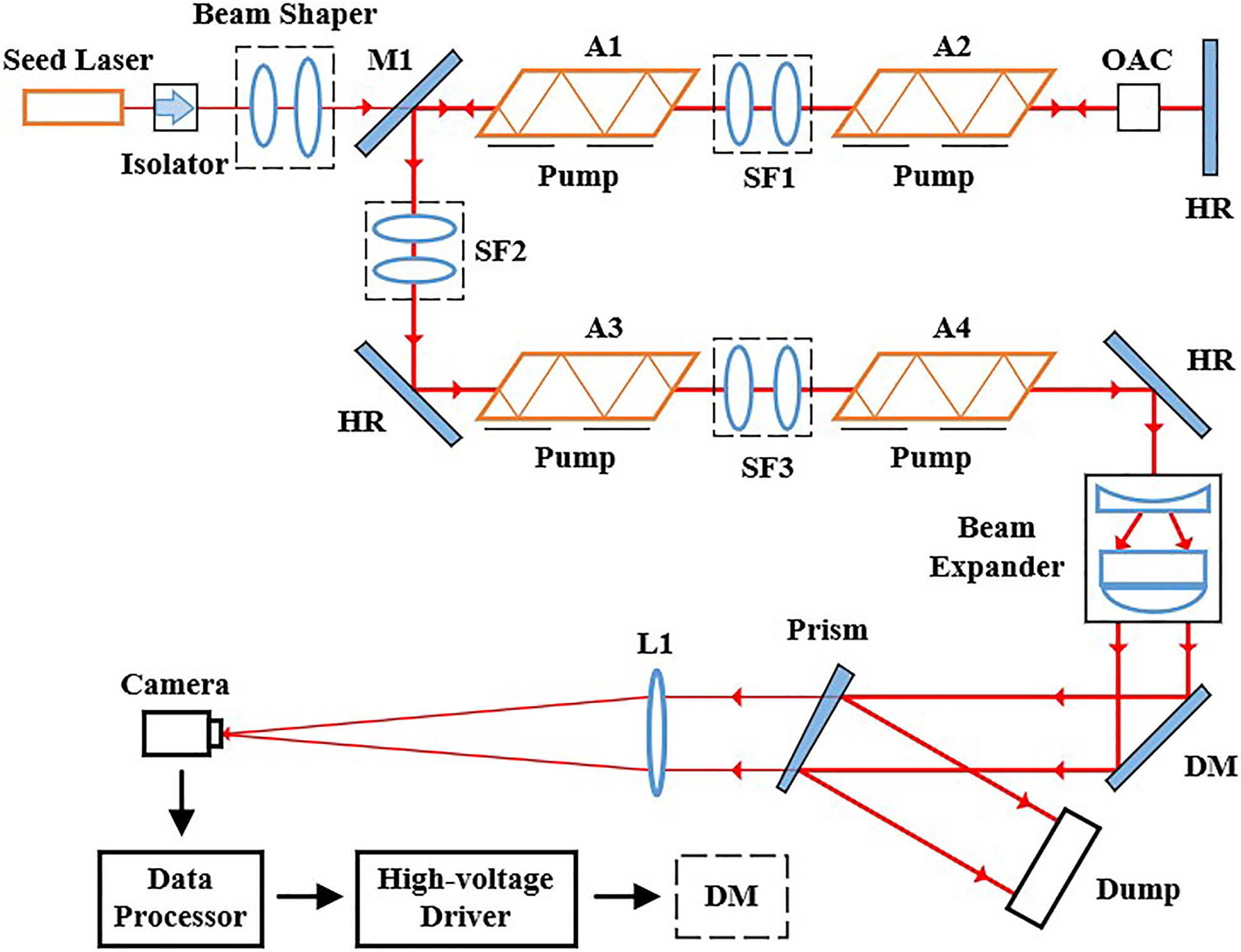
The configuration of the MOPA system with an AO control part is shown in Fig. 1. A Yb-doped fiber laser and 4 slab Yb:YAG amplifiers form the main parts of the MOPA configuration, making it power-scalable. The AO control part consists of a collimating lens, a camera, a high-voltage driver, and a data processor. The seed laser (Shanghai Institute of Optics and Fine Mechanics, a Yb:YAG-doped fiber laser) has a wavelength of 1030 nm, a power of 1 kW, and a horizontal beam quality of 1.15 times the diffraction limit. The pulse duration and repetition of the seed laser are 200 μs and 1000 Hz, respectively. The seed laser first passes through an isolator to prevent damage from the returned light, and then is shaped by a beam shaper. The transmission laser through a polarizing mirror (M1) is amplified by four Yb:YAG amplifiers (A1, A2, A3, and A4), each of which has a 45 mm × 6 mm × 87 mm face-pumped Yb:YAG crystal with a Yb-doped concentration of 1 at.%. To prevent the amplified laser from propagating back, M1 is transparent to the p-polarized light and reflective to the s-polarized light at the incident angle of 45°, and an optically active crystal (OAC) is used to change the polarization state of the laser reflected by the high-reflection (HR) mirror to the s-polarization. The outside view of an amplification component employed in the MOPA structure is shown in Fig. 2, with the cooling system included. The crystal is a quasi-right-parallelepiped with four rectangular faces and two parallelogram faces. The two 45 mm × 87 mm rectangular side faces are parallel to each other, while the two 6 mm × 87 mm parallelogram side faces are approximately parallel with an angle of 5° to suppress the parasitic oscillations. The pump laser, working at a 940 nm wavelength, a 200 μs pulse duration, and a 1000 Hz repetition rate, is beam-shaped into a 40 mm ×82 mm quasi-rectangle. To improve the absorption of the pump laser, the 45 mm × 87 mm pumping side face is anti-reflection (AR)-coated and the opposite face is HR-coated at 940 nm. The two 45 mm × 6 mm rectangular faces (i.e., the end faces of the crystal) are AR-coated at 1030 nm, are parallel to each other, and form an angle of 56° with respect to the 45 mm × 87 mm pumping side face. In each crystal, the laser propagates in a zigzag structure. A double-pass structure is adopted by A1 and A2, which could improve energy extraction efficiency. The laser generated by A1 and A2 is reflected by two HR mirrors and then reaches single-pass A3 and A4. Three spatial filters (SF1, SF2, and SF3) are used to suppress the high spatial-frequency component of the laser beam, with each one placed between every two amplifiers. The power loss of the SF is about 2%. Each spatial filter is composed of two identical 100 mm × 50 mm rectangular lenses with the same 800 mm focal length and an aperture at their common focus. The two lenses form a 4f image-relay system. In the amplification process, the amplified power of the MOPA system increases with the pump power linearly, as shown in Fig. 3(a). To give the MOPA system an output power of 21.2 kW (with the peak power to be 106 kW), 5.3 kW of power is extracted from each crystal and the total pump power reaches 70 kW, corresponding to an optical-to-optical conversion efficiency of 30%.
Sign up for Chinese Optics Letters TOC. Get the latest issue of Chinese Optics Letters delivered right to you!Sign up now

Figure 1.Configuration of the laser based on a MOPA system with an AO control part.
Figure 2.Outside view of an amplification component.
Figure 3.(a) Output power and (b) beam quality of the laser without AO control.
For subsequent laser applications, the output beam of the MOPA system is expanded to a rectangle of 216 mm × 96 mm through a beam expanding component. The total power loss of the beam expanding component is about 1%. The expanded beam is corrected by the following AO control part, and then reflected by the prism for other applications. In the AO control part, a lab-manufactured DM is adopted to meet the correction requirement of the rectangular beam with a length-width ratio of 2:1. The DM, 226 mm × 106 mm in size, comprises 241 hexagonally distributed actuators. The mirror of the DM is HR-coated with a reflection of more than 99.5 %. The total power loss of the AO control part is less than 1%. The rest of the beam is collected by a complementary metal-oxide-semiconductor (CMOS) camera (acA2000-340kmNIR of Basler, 2048 × 1088 pixels, 11.3 mm × 6 mm sensor size) through a lens (L1, 1900 mm focal length, 300 mm diameter). The far-field spot intensity distribution of the laser beam is recorded by the CMOS camera and transferred to the data processor for calculation of the beam quality. After the calculation, the control signals are transmitted to the high-voltage driver to apply voltages to the DM actuators. Wavefront compensation for the laser beam is made by the DM. To describe the beam quality of the laser, we use horizontal beam quality (HBQ), which is given by the ratio of the actual beam radius at a given power (86.5% of the total power) to the ideal beam radius at the same power[20]. The HBQ of the laser increases monotonically with the output power and reaches up to 4.2 times the diffraction limit when the output power is 21.2 kW, as shown in Fig. 3(b).
The outside view of the DM used in the AO control part to improve the beam quality of laser is shown in Fig. 4(a) and the actuators’ distribution of the DM is shown in Fig. 4(b). The 241 actuators of the DM are hexagonally distributed, and the intervals between adjacent actuators are 12 mm along the long side direction and 8 mm along the short side direction. The effective area of the mirror matches up with the area covered by the incident beam with a size of 216 mm × 96 mm. With a high density of actuators, the DM is quite capable of correcting such a rectangular beam. Meanwhile, the correction frequency of the DM could reach up to 200 Hz, which ensures real-time correction.
Figure 4.(a) Outside view and (b) actuator distributions of the DM.
To investigate the aberration correction ability of the DM for the rectangular beam, simulation analysis has been carried out by using the 3rd to 15th Zernike mode aberrations as initial values to be corrected. The least square method is used as the calculation algorithm for the correction. The results of the correction are shown in Fig. 5, using the 3rd, 7th, and 11th Zernike mode aberrations as a demonstration. The results of the peak-to-valley (PV) values and root-mean-square (RMS) values before and after the wavefront correction are shown in Fig. 6.
Figure 5.Wavefront correction results of Zernike mode aberrations. (a) 3rd before and (b) after correction. (c) 7th before and (d) after correction. (e) 11th before and (f) after correction.
Figure 6.(a) PV and (b) RMS correction results of Zernike mode aberrations.
As displayed in Fig. 6, the initial PV values of the Zernike mode aberrations are set to 1 μm, and the best correction result is 0.0432 μm for the 8th Zernike mode aberration, with a 96% reduction. The PV values after correction are reduced by 92% on average. For the RMS values, the best correction result is 0.0500 μm for the 7th Zernike mode aberration with a 98% reduction, while the average reduction is 97%.
Besides the wavefront, the correction ability of the DM for the far-field spot distribution of the 3rd to 15th Zernike mode aberrations is also investigated. HBQ results of the far-field spot distribution correction are shown in Fig. 7 using the 3rd, 7th, and 11th Zernike mode aberrations as a demonstration. As shown in Fig. 7(a), the HBQ of the initial far-field spot distribution is 4.06 times the diffraction limit, and the far-field spot distribution is diffuse. As shown in Fig. 7(b), after correction of the 3rd Zernike mode aberration, the HBQ of the corrected far-field spot distribution is 1.10 times the diffraction limit with a 73% reduction, and the far-field spot distribution is concentrated. Detailed HBQ results of the correction for 3rd to 15th Zernike mode aberrations are shown in Fig. 8. It could be seen that the HBQ reduction after the correction is 69% on average. The correction results of both the wavefront and the far-field spot distribution show that the DM is capable of aberration correction for a rectangular laser beam.
Figure 7.Far-field spot distribution correction results of Zernike mode aberrations. (a) 3rd before and (b) after correction. (c) 7th before and (d) after correction. (e) 11th before and (f) after correction.
Figure 8.HBQ correction results of Zernike mode aberrations.
In the MOPA system shown in Fig. 1, the output laser is a 216 mm × 96 mm rectangular beam with an HBQ of 4.20 times the diffraction limit. After reflection and correction by the DM, the laser is partly reflected by the prism for further applications. The far-field spot distribution of the transmission laser through the prism is measured by the CMOS camera of the AO control part to calculate the beam quality (i.e., the HBQ). In the closed-loop correction process, the stochastic parallel gradient descent (SPGD) algorithm is adopted and the DM generates a wavefront to compensate the aberration. In the SPGD algorithm, the HBQ of the far-field spot distribution and the voltage values of the DM’s actuators are taken as the system performance value and the iteration variation vector, respectively. In each iteration, the iteration variation factor is updated with a random perturbation in the value until the system performance value converges to a stable one. Finally, the voltage values of the actuators are fixed and the compensative wavefront is achieved.
Figure 9 demonstrates the output laser beam and the respective intensity distribution of the far-field spot at 21.2 kW without and with the correction. Without the AO correction, the intensity of the far-field spot is unevenly distributed and is diffuse in a certain area with an HBQ of 4.20 times the diffraction limit, and the beam size is 473 μm × 297 μm. With the AO correction, the intensity distribution is highly concentrated and the uniformity of the spot is improved, with the HBQ of 1.94 times the diffraction limit and the beam size of 44 μm × 55 μm.
Figure 9.(a) Output laser beam. Far-field spot distribution of output laser beam (b) without and (c) with AO correction.
As shown in Fig. 9, the laser is well corrected by the DM, and the beam quality is controlled below 2 times the diffraction limit. With the AO correction, the high-power laser generated by the Yb:YAG MOPA system could maintain a good beam quality. Meanwhile, the power of the laser is scalable by using multi-stage amplifiers.
In conclusion, a quasi-continuous-wave 21.2 kW laser with a beam quality of 1.94 times the diffraction limit is realized through a multi-stage AO-controlled MOPA system. A seed laser and four amplifiers are employed in the MOPA configuration, with a pulse duration of 200 μs and a repetition rate of 1000 Hz. An AO control part is adopted to improve the beam quality at high power. A rectangular beam is generated and amplified by the MOPA system, corrected by the AO control part, and finally developed into a 21.2 kW, 216 mm × 96 mm output beam with 1.94 times the diffraction-limited beam quality. To our knowledge, this is the best quality laser in the 20 kW class except for combined lasers.
References
[1] E. M. Birger, G. V. Moskvitin, A. N. Polyakov, V. E. Arkhipov. Weld. Int., 25, 234(2011).
[2] R. Cottam, M. Brandt. Phys. Procedia, 12, 323(2011).
[3] D. Douay, F. Daniere, R. Fabbro, L. Sabatier. Proc. SPIE, 2789, 202(1996).
[4] T. Ishide, S. Tsubota, M. Nayama, Y. Shimokusu, T. Nagashima, K. Okimura. Proc. SPIE, 3888, 543(2000).
[5] M. Sparkes, M. Gross, S. Celotto, T. Zhang, W. O’Neill. Proc. ICALEO, 2006, 197(2006).
[6] A. Riveiro, F. Quintero, F. Lusquiños, J. Pou, M. Pérez-Amor. J. Laser Appl., 20, 230(2008).
[7] X. Z. Zhang, S. S. Xie, Q. Ye, Z. L. Zhan. Chin. Opt. Lett., 5, 235(2007).
[8] J. R. Cook, J. R. Albertine. Proc. SPIE, 2988, 264(1997).
[9] J. Shwartz, G. T. Wilson, J. M. Avidor. Proc. SPIE, 4632, 10(2002).
[10] M. J. Lavan, J. J. Wachs. Proc. SPIE, 8187, 818704(2011).
[11] B. Wattellier, J. Fuchs, J. P. Zou, K. Abdeli, C. Haefner, H. Pépin. Rev. Sci. Instrum., 75, 5186(2004).
[12] A. Kudryashov, A. Alexandrov, A. Rukosuev, V. Samarkin, P. Galarneau, S. Turbide, F. Châteauneuf. Appl. Opt., 54, 4352(2015).
[13] L. C. Sun, T. H. Liu, X. Fu, Y. D. Guo, X. J. Wang, C. F. Shao, Y. M. Zheng, C. Sun, S. B. Lin, L. Huang. Chin. Opt. Lett., 17, 051403(2019).
[14] L. C. Sun, Y. D. Guo, C. F. Shao, Y. Li, Y. M. Zheng, C. Sun, X. J. Wang, L. Huang. Opt. Lett., 43, 4160(2018).
[15] G. D. Goodno, H. Komine, S. J. McNaught, S. B. Weiss, S. Redmond, W. Long, R. Simpson, E. C. Cheung, D. Howland, P. Epp, M. Weber, M. McClellan, J. Sollee, H. Injeyan. Opt. Lett., 31, 1247(2006).
[16] Z. Z. Chen, Y. T. Xu, Y. D. Guo, B. S. Wang, J. Xu, J. L. Xu, H. W. Gao, L. Yuan, H. T. Yuan, Y. Y. Lin, Y. S. Xiao, Y. Bo, Q. J. Peng, W. Q. Lei, D. F. Cui, Z. Y. Xu. Appl. Opt., 54, 5011(2015).
[17] L. Xu, Y. C. Wu, Y. L. Du, D. Wang, X. C. An, M. Li, T. J. Zhou, J. L. Shang, J. T. Wang, Z. W. Liu, L. Ou, N. Zhao, R. J. Xiang, L. X. Tong, H. H. Lin, Q. S. Gao, Y. H. Lu, K. Zhang, C. Tang. Opt. Express, 26, 14592(2018).
[18] D. Wang, Y. L. Du, Y. C. Wu, L. Xu, X. C. An, L. Q. Cao, M. Li, J. T. Wang, J. L. Shang, T. J. Zhou, L. X. Tong, Q. S. Gao, K. Zhang, C. Tang, R. H. Zhu. Opt. Lett., 43, 3838(2018).
[19] J. Eggleston, T. Kane, K. Kuhn, J. Unternahrer, R. Byer. IEEE J. Quantum Electron., 20, 289(1984).
[20] H. C. Miller. Opt. Express, 20, 28819(2012).