
Jiachuan Yang, Rongwei Liu, Xiaopeng Xie. Low phase noise microwave signal generation with microcombs (Invited)[J]. Infrared and Laser Engineering, 2022, 51(5): 20220236
- Infrared and Laser Engineering
- Vol. 51, Issue 5, 20220236 (2022)
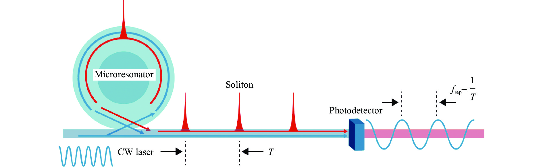
Fig. 1. Experimental set-up diagram of microwave signal generation system based on microcomb
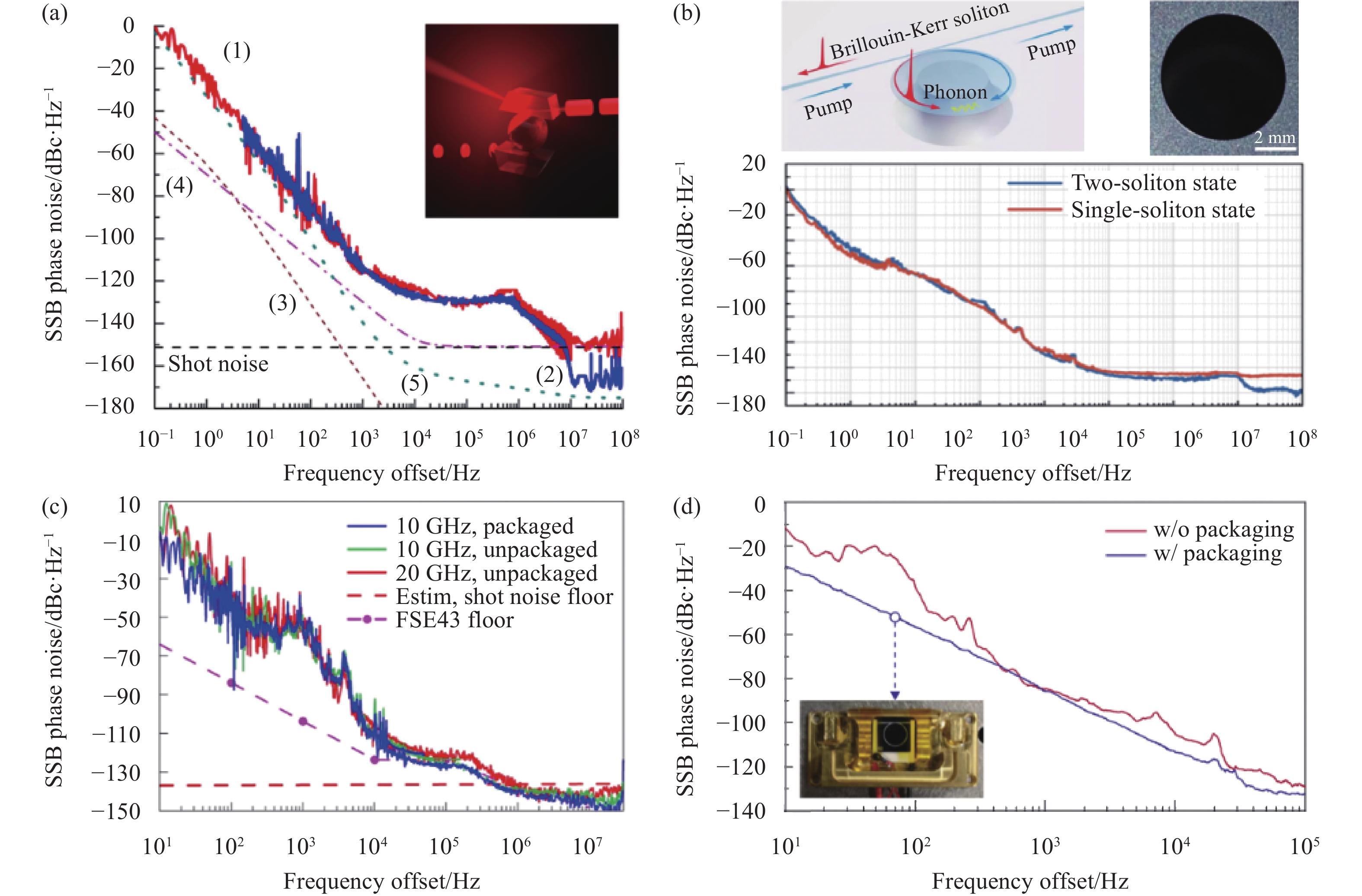
Fig. 2. Microwave signal generation based on beat signals of microcombs. (a)-(d) Frequency comb microwave signal generator based on
microresonator, microcomb microwave signal generator based on Brillouin assisted stabilization, chip-scale microwave signal generator, frequency comb microwave signal generator based on silica disk microresonator respectively. The five lines in Fig.(a), phase noise of microwave signal without and with(red line, (1)) and with(blue line, (2)) a narrow-band filter-placed after the photodetector. Curves(3) and (4) describe theoretically found fundamental thermorefractive and quantum noise of the oscillator, sensitivity of phase noise analyzer is described by curve(5)
基于微腔光频梳拍频的微波信号产生。(a)~(d)分别基于氟化镁微腔的光频梳微波信号发生器、基于布里渊辅助稳定的光频梳微波信号发生器、芯片级微波信号发生器、基于二氧化硅微盘腔的光频梳微波信号发生器。图(a)中五条曲线分别为:(1)光电探测器后无窄带滤波器时的微波信号相位噪声(红线),(2)光电探测器后有窄带滤波器时的相位噪声(蓝线),(3)、(4)分别是振荡器热折射噪声理论极限与量子噪声理论极限,(5)相位噪声仪底噪
Fig. 3. [in Chinese]
Fig. 3. Microwave signal generation based on the microcomb division frequency. (a) and (c), (b) and (d), (e) and (g), (f) and (h) Millimetre wave oscillator based on Brillouin Stokes division frequency, measurement device of timing jitter based on optical fiber delay line interferometer, microwave signal generator based on optical fiber photonic stabilisation method, microwave generator using a microcomb-based transfer oscillator. The three lines in Fig.(b), measured timing jitter[curve(i)], projected timing jitter from soliton relative intensity noise [curve (ii)] and computed quantum limit of timing jitter [curve (iii)]. The lines in Fig.(d), absolute single-sideband (SSB) phase noise of the 14.09 GHz signal via the Kerr comb transfer oscillator (blue line) and obtained directly from the Kerr comb repetition rate (green line). The red line is the limit inferred from the optical phase noise of the ultra-stable laser
Fig. 3. [in Chinese]

Set citation alerts for the article
Please enter your email address
© Copyright 2018-2021 | Chinese Laser Press. All Rights Reserved 沪ICP备15018463号-20