1School of Physics and Key Laboratory of Weak-Light Nonlinear Photonics, Nankai University, Tianjin 300071, China
2National Laboratory of Solid State Microstructures, School of Physics, and Collaborative Innovation Center of Advanced Microstructures, Nanjing University, Nanjing 210093, China
In free-space or in optical fibers, orbital angular momentum (OAM) multiplexing for information transmission has been greatly developed. The light sources used were well coherent communication bands, and the fibers used were customized. Here, we use an 810 nm femtosecond laser to generate optical vortices carrying OAM and then feed them into two kinds of commercial step-index few-mode fibers to explore the transmission characteristics of OAM modes. We also propose a method without multiple-input multiple-output digital signal processing to identify the input OAMs. It is of great guiding significance for high-dimensional quantum information experiments via the OAMs as a degree of freedom, using the light generated by the spontaneous parametric down-conversion as the source and the commercial fibers for information transmission.
In recent years, with the rapid development of internet, cloud computing, large data centers, and Internet of Things applications, the demand for network bandwidth has shown a relatively high-speed growth trend, and the surge of network traffic has brought great challenges to information and communication networks. The expansion technology of fiber communication networks will become the key to coping with the dramatic growth of network data streams. The existing optical network expansion technologies, such as wavelength-division multiplexing (WDM), frequency-division multiplexing (FDM), time-division multiplexing (TDM), and polarization-division multiplexing (PDM) all use single-mode fibers (SMFs) as transmission media[1–3]. However, with the continuous development and progress of these technologies, the nonlinear effect of SMFs is aggravated, and their capacity gradually approaches the nonlinear Shannon limit[4]. Therefore, the expansion of fiber communication requires space-division multiplexing (SDM) based on spatial dimensions. SDM has been shown to be a promising way in free-space and fiber communications[5–7].
Mode-division multiplexing (MDM), as a subset of SDM, has attracted research interest, because it can increase the data transmission capacity in fibers. Many mode bases can be used in MDM, where the orbital angular momentum (OAM) mode is a special mode base that has received wide attention[8]. An OAM mode with a helical phase of carries an OAM of per photon, where is the topological charge, is the reduced Planck constant, and is the azimuthal angle[9], respectively. In principle, can take any integer ranging from to , and OAM modes with different are intrinsically orthogonal, which provides the potential of applying OAM as a degree of multiplexing freedom to achieve the higher capacity.
OAM multiplexing in specially designed fibers has been demonstrated without multiple-input multiple-output digital signal processing (MIMO-DSP)[10]. OAM multiplexing with large crosstalk in few-mode fibers (FMFs) has been also demonstrated by MIMO-DSP[11,12]. Although the specially designed fibers for transmitting the OAM modes can dramatically inhibit the inter-mode crosstalk without MIMO-DSP[13], it is difficult to produce them on a large scale because of their complex structure and high manufacturing cost. Therefore, the most promising fibers for transmitting the OAM modes are still commercial step-index and graded-index fibers. In recent years, there have been some reports on MDM in the above two kinds of fibers, showing impressive performance[14–16]. In addition, with the development of high-dimensional quantum cryptography[17], the demand for single-channel information carrying capacity in quantum optics experiments is also increasing. Considering that many devices, such as silicon avalanche photodiodes (Si-APDs) single-photon detectors, have high efficiency and low noise near 810 nm, this band is widely used in quantum information experiments[18].
Sign up for Chinese Optics Letters TOC. Get the latest issue of Chinese Optics Letters delivered right to you!Sign up now
Here, we use a femtosecond (fs) laser at a central wavelength of 810 nm with pulse duration of and a repetition rate of 80 MHz, as light source, to generate the OAM modes. We couple the OAM modes with different topological charges into two kinds of commercial step-index fibers (G652B and OFS-1550TMF), respectively. For the G652B fiber, it is an SMF at 1310 nm, but becomes a two-mode fiber (TMF) at 810 nm we used here. We explore the propagation characteristics of the OAM modes in the G652B and OFS-1550TMF FMFs at 810 nm. We find that during the transmission, the handedness of the OAM mode is hard to be maintained completely, but its absolute value (i.e., topology of the OAM mode) can be protected. Because of this characteristic, we present to identify the absolute value of the OAM mode (i.e., topology), which is MIMO-DSP free.
Under the scalar approximation, linearly polarized (LP) modes are eigenmodes in the weakly guiding fibers. Using the vector wave equation, the vector eigenmodes can be obtained. The fundamental mode LP01 can be decomposed into two orthogonally polarized and with the degenerate effective refractive index (i.e., degenerate propagation constant). The first high-order solution under the scalar approximation can be decomposed into four vector-mode bases of , , and . and are degenerate because their effective refractive-index difference is only , while and are non-degenerate. For the high-order mode , the vector-mode bases of and as well as and are degenerate, respectively. In another word, these vector eigenmodes are divided into two different groups.
We now discuss the propagation characteristics of OAM modes in G652B and OFS-1550TMF FMFs. The axial symmetry of the OAM modes makes them more efficient in coupling with fibers. For the first-order and high-order OAM modes[19–21], we have and where and represent the left- and right-handed circularly polarized components, respectively.
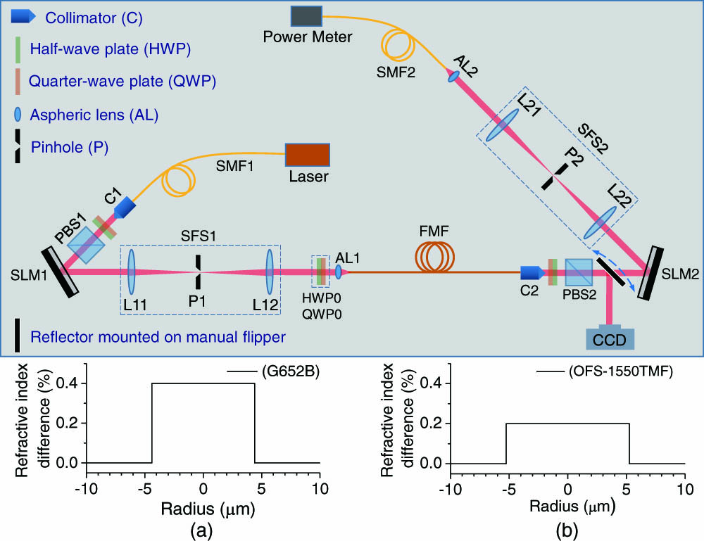
The experimental setup is shown in Fig. 1, in which the light source is a fs laser at a central wavelength of 810 nm with a pulse duration of , a repetition rate of 80 MHz, and a spectral width of . The output beam from the fs laser is coupled into SMF1 to perform the spatial filtering and to preserve the fundamental Gaussian mode. The output beam from SMF1 is collimated by C1, and then its polarization state is controlled by the first set of quarter-wave plates (QWPs), half-wave plates (HWPs), and polarizing beam splitter (PBS1) to be horizontally polarized, due to the requirement of spatial light modulator (SLM1). The first-order diffraction from the forked grating loaded on SLM1 is extracted by spatial filtering system (SFS1), which includes P1 and a system composed of L11 and L12. The extracted first-order diffraction with a helical phase of is a horizontally polarized vortex beam carrying an OAM of per photon. The set of HWP0 and QWP0 changes the LP vortex beam to be circularly polarized. After focusing by an aspheric lens (AL1) of , the circularly polarized vortex beam is coupled into an FMF (G652B or OFS-1550TMF). The output beam from the FMF is collimated by C2 and then is converted by the second set of QWP, HWP, and PBS2 to be horizontally polarized. We now need to measure the propagation characteristics of OAM modes in FMFs. The measurement involves two steps: (i) the measurement of the intensity pattern and (ii) the projection measurement of OAMs. The two measurement steps can be switched on/off by the reflector mounted on a manual flipper. When the reflector is inserted into the beam path, the intensity patterns will be detected by a CCD. When the reflector is lifted, the beam is incident on SLM2, and the projection measurement of OAMs can be carried out. To perform the projection measurement of the OAM spectrum, the forked gratings with different topological charges are loaded on SLM2 in turn. The OAM component we want to measure of the output beam from the FMF can be converted by the forked grating with the suitable topological charge into the fundamental Gaussian mode that is the first-order diffraction from SLM2. It is extracted and filtered by SFS2, which includes P2 and another system composed of L21 and L22. The extracted fundamental Gaussian mode is coupled by AL2 into SMF2 and then is detected by the power meter. One should point out that in all the experiments below, the beams incident into the FMFs are all right-handed circularly polarized.
Figure 1.Diagrammatic sketch of experiment setup. Laser, fs laser at a central wavelength of 810 nm with pulse duration of and repetition rate of 80 MHz; PBS, polarizing beam splitter; SLM, spatial light modulator; L11, L12, L21 and L22, lenses with the same focal length of 100 mm; AL1 and AL2, aspheric lenses; SFS, spatial filtering system; SMF, single-mode fiber; FMF, few-mode fiber; CCD, charge coupled device. Insets (a) and (b) show the refractive-index difference profiles of the G652B and OFS-1550TMF fibers, respectively.
In addition, we need to slightly adjust the orientations of QWP0 and HWP0 to reduce the mode coupling as much as possible when the vortex beam carrying a certain OAM propagates in the FMF, which is in fact equivalent to diagnosing the propagation matrix. It reduces the large number of MIMI-DSP caused by unnecessary mode coupling.
We first explore the propagation behavior of vortex beams carrying OAM in the G652B fiber. For the light at a wavelength of 810 nm, the G652B fiber is a TMF. As shown in the first row of Fig. 2(a), the holograms loaded on SLM1, corresponding to the forked gratings with , 0, 1, are used to generate three vortex beams carrying OAMs of , 0, 1 (in the units of ), as shown in the second row of Fig. 2(a). Each of the three vortex beams is coupled into three G652B fibers with different lengths (15, 150, and 1500 m), respectively. The total intensity patterns of the output beam from the G652B fibers are shown in the last three rows of Fig. 2(a). One can see that for the input beam with , the output beams from the three different-length G652B fibers exhibit all near Gaussian profiles (with the respective transmittances of 78%, 71%, and 52%).
Figure 2.Experimental results of right-handed circularly polarized vortex beams with OAM passing through the G652B fibers with different lengths. (a) From top to bottom, it depicts the holograms loaded on the SLM (from left to right depicts input ), generated mode intensity profiles after passing the system, intensity profiles output from 15, 150, and 1500 m optical fiber, respectively. Then, (b), (c), and (d) are projection measurements corresponding to the last three rows of (a), respectively.
However, for the input beams with , the output beams have different profiles for the three different-length G652B fibers. As shown in Fig. 2(a), the intensity patterns can be decomposed into two components, one is paired half-moons (with its intensity ) and the other is donut-like background (with its intensity ). For the case of input , the contrast of the paired half-moons is low (relative to the case of incident with the same length) and changes little with the increase of propagation length. However, for the case of input , when the propagation length order is less than kilometers, the contrast of the paired half-moons does not monotonically change, but when propagation length is longer than kilometers, the contrast obviously decreases. The reasons will be elaborated on below.
In order to quantify the analysis, we carry out the projection measurement of the OAM spectra of the output beams from three different-length G652B fibers. The measured matrices are shown in Figs. 2(b)–2(d), corresponding to the fiber lengths of 15, 150, and 1500 m, respectively. Each element of the matrices is the percentage of normalized intensity. In the case of the 15 m G652B fiber, we can see that for the input (0 and 1), the output component of (0 and 1) has the largest fraction of 70.7% (77.2% and 63.4%). In other words, the dominant component of the OAM spectrum of the output beam is the same as that of the input beam. In contrast, for the two cases of 150 m and 1500 m G652B fibers, the situations are different. In the 150 m G652B fiber, for the case of the input (), the strongest OAM component of the output beam is (), which is different from (the same as) the input OAM. In the 1500 m G652B fiber, more fraction of the input beam of () is converted into the mode of (), with the fraction of 38.5% (42.7%). That is to say, the maximum component in the OAM spectrum of the output beam is reversed with respect to the input OAM value. However, for the case of the input , the strongest OAM component of the output beam is still , a smaller fraction of the input beam is converted into the components with and 1, and the fraction is slightly increased from 22.8% to 27.7% by increasing the fiber length from 15 m to 1500 m.
In the TMF as the G652B fiber, as shown in Eq. (1), the right-handed circularly polarized () mode is decomposed into (). After calculating, we obtain an effective refractive-index difference of between and , while that of is between and . During the propagation, therefore, the beat frequency formed by and is times that formed by and . The handedness of OAM cannot be maintained in the G652B fibers, but the absolute value of OAM can be maintained.
We now explore the propagation characteristics of the vortex beam carrying the OAMs in the OFS-1550TMF fiber. For the high-order modes, the only two groups of effective refractive indices for any order modes, as mentioned above, and as well as and are degenerate, respectively. The first rows of Figs. 3(a) and 3(b) are the forked gratings for generating the input beams carrying different OAMs. The second rows of Figs. 3(a) and 3(b) correspond to the intensity patterns of the input beams (carrying OAMs from to 5) before entering the OFS-1550TMF fiber. The third rows of Figs. 3(a) and 3(b) show the intensity patterns of horizontal LP components of the output beams from the OFS-1550TMF fiber. We can find the following characteristics: (i) for the input beams of , the number of strong spots in the azimuthal direction is instead of ; (ii) when the two input beams carry the opposite OAMs, the intensity patterns of both output beams are complementary; (iii) for the two input OAMs with the same order but opposite signs, one of the two outputs has the higher contrast, but the other has the lower one. That is to say, the two contrasts cannot be maximized at the same time.
Figure 3.Experimental results of light with OAM passing through OFS-1550TMF optical fibers of 150 m length. The graph is divided into two parts: (a) corresponds to , 1, 2, 3, 4, and 5, and (b) corresponds to , and . Each part is divided into three rows, corresponding to grating, and the intensity distribution of incident light and emitted light, respectively.
From the projection measurement result of the OAM spectra of the output beams, as shown in Fig. 4(a), we find the following characteristics. (i) Similar to the phenomena observed in the G652B fiber, for the input beams with , the OAM spectra of the output beams from the OFS-1550TMF fiber have two output maxima with , respectively. The OAM spectra exhibit the broadening phenomena. (ii) Except for the four input beams with , and 5, the output OAM spectrum of any one with among the other seven input beams has the two local maximum components of . (iii) Except for the two input beams with and 5, the output OAM spectrum of any one with among the other nine input beams has the strongest component of . Therefore, the OAM value of the input beam can be identified or diagnosed according to the OAM spectrum of the output beam.
Figure 4.OAM spectra of the output beams from the OFS-1550TMF fiber and the encoding results. (a) shows the results of projection measurement for the input beams with , and . If , 1, 2, 3, 4, 5 are used for encoding, the results are shown in (b), and if are used for encoding, the results are shown in (c).
From the projection measurement results, it is not difficult to understand the reason why the intensity patterns of the output beams exhibit the ring multi-spot distribution, which originates from the interference between the components of and . The background is still a donut-like intensity ring because of the different intensities of the components with and .
Based on the experimental results, we find that although the handedness of OAM cannot be maintained during the transmission process in the FMFs, the topology (the absolute value of OAM) can be maintained, which is independent of the fiber length. Therefore, if the OAM is used to encode the parameters, it is easy to introduce the error codes. However, we can use the intensity sum of the OAM components with the opposite of the output beam from the FMF to identify or diagnose the absolute value of OAM of the input beam. We then propose to use the topological property of OAM for encoding. As shown in Figs. 4(b) and 4(c), the input beams with , 1, 2, 3, 4, 5 (or ) correspond to six codes. In other words, the topological property of the input beam can be identified or diagnosed by the OAM (absolute) value corresponding to the strongest component in the OAM spectrum of the output beam. Correspondingly, the coding can be decoded. We find that although the topological coding loses a half of the available channel capacity, it brings obvious advantages. (i) It has the higher contrast, stronger anti-jamming ability, and higher robustness. (ii) Although the OAM spectrum of the output beam is related to the length of fiber, the topological property of OAM is independent of the length of fiber. (iii) If encoding with the OAM, the sender and the receiver should “negotiate” the encoding list in advance; but, encoding with the topological property of OAM does not require “negotiation”. (iv) The input codes can be determined directly from the strongest component of the output OAM spectrum, without resorting to the inefficient MIMO-DSP process.