• Chinese Journal of Lasers
  • Vol. 48, Issue 4, 0401011 (2021)
Xiang Han, Xinlin Chen, Wei Xiong, Tengfang Kuang, Zhijie Chen, Miao Peng, Guangzong Xiao*, Kaiyong Yang, and Hui Luo
Author Affiliations
  • College of Advanced Interdisciplinary Studies, National University of Defense Technology, Changsha, Hunan 410073, China
  • show less
    DOI: 10.3788/CJL202148.0401011 Cite this Article Set citation alerts
    Xiang Han, Xinlin Chen, Wei Xiong, Tengfang Kuang, Zhijie Chen, Miao Peng, Guangzong Xiao, Kaiyong Yang, Hui Luo. Vaccum Optical Tweezers System and its Research Progress in Precision Measurement[J]. Chinese Journal of Lasers, 2021, 48(4): 0401011 Copy Citation Text show less
    Classification of the optical force models
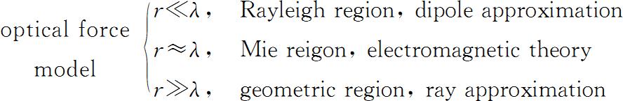
    Fig. 1. Classification of the optical force models
    Schematic diagram of the optical tweezers in vacuum. (a) Single-beam optical tweezers; (b) dual-beam optical tweezers
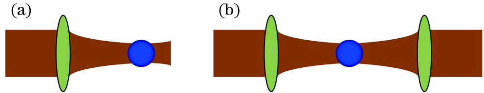
    Fig. 2. Schematic diagram of the optical tweezers in vacuum. (a) Single-beam optical tweezers; (b) dual-beam optical tweezers
    Schematic diagram of the single-beam optical tweezers system with vertical upward[66]
    Fig. 3. Schematic diagram of the single-beam optical tweezers system with vertical upward[66]
    Schematic diagram of the single-beam optical tweezers system with a parabolic mirror[67]
    Fig. 4. Schematic diagram of the single-beam optical tweezers system with a parabolic mirror[67]
    Influence of the misalignment distance d in the double-beam optical tweezers on the behavior of capturing microspheres. (a) When d=0, the microsphere is stably captured at the center of the optical tweezers; (b) when 0dd1, the microsphere spirals to the center; (c) when d≥d1, the microsphere rotates around the center[36]
    Fig. 5. Influence of the misalignment distance d in the double-beam optical tweezers on the behavior of capturing microspheres. (a) When d=0, the microsphere is stably captured at the center of the optical tweezers; (b) when 0<d<d1, the microsphere spirals to the center; (c) when dd1, the microsphere rotates around the center[36]
    Principle diagram of the integrated optical tweezers. (a) Cross-section of the waveguide; (b) image of the waveguide cross-section by scanning electron microscopy; (c) spot pattern in the waveguide; (d) top view of optical tweezers using waveguides when coupling red light; (e) microscopic view of optical tweezers using waveguides[69]
    Fig. 6. Principle diagram of the integrated optical tweezers. (a) Cross-section of the waveguide; (b) image of the waveguide cross-section by scanning electron microscopy; (c) spot pattern in the waveguide; (d) top view of optical tweezers using waveguides when coupling red light; (e) microscopic view of optical tweezers using waveguides[69]
    Schematic diagram of the particle loading structure by piezoelectric ceramics[71]
    Fig. 7. Schematic diagram of the particle loading structure by piezoelectric ceramics[71]
    Schematic diagram of the single-microsphere launching by pulsed lasers[72]
    Fig. 8. Schematic diagram of the single-microsphere launching by pulsed lasers[72]
    Principle diagram of the back focal plane displacement measurement[80]
    Fig. 9. Principle diagram of the back focal plane displacement measurement[80]
    Displacement measurement using lateral scattered laser on back focal plane[39]
    Fig. 10. Displacement measurement using lateral scattered laser on back focal plane[39]
    Schematic diagram of the displacement detection by balanced detectors[16]
    Fig. 11. Schematic diagram of the displacement detection by balanced detectors[16]
    Principles of back-light interference displacement measurement method[83]
    Fig. 12. Principles of back-light interference displacement measurement method[83]
    Basic process of optical tweezers feedback control
    Fig. 13. Basic process of optical tweezers feedback control
    Principle of the optical momentum feedback[16]
    Fig. 14. Principle of the optical momentum feedback[16]
    Schematic diagram of the parameter feedback scheme[17]
    Fig. 15. Schematic diagram of the parameter feedback scheme[17]
    Diagram of the feedback cooling scheme by electrostatic forces[19]
    Fig. 16. Diagram of the feedback cooling scheme by electrostatic forces[19]
    Diagram of the cavity feedback cooling scheme. (a) Light path of the feedback cooling scheme; (b) light transmission[16]
    Fig. 17. Diagram of the cavity feedback cooling scheme. (a) Light path of the feedback cooling scheme; (b) light transmission[16]
    Schematic diagram of the self-feedback intracavity optical tweezers. (a) Intracavity optical tweezers without trapped particles; (b) when trapped particles are located in the center of optical tweezers; (c) when trapped particles are offset from the center of optical tweezers [86]
    Fig. 18. Schematic diagram of the self-feedback intracavity optical tweezers. (a) Intracavity optical tweezers without trapped particles; (b) when trapped particles are located in the center of optical tweezers; (c) when trapped particles are offset from the center of optical tweezers [86]
    Quality factors of the different resonance subsystems[32]
    Fig. 19. Quality factors of the different resonance subsystems[32]
    Sensing system of the vacuum optical tweezers. (a) Experimental device; (b) optical tweezers force corresponding to axial offset; (c) time series curve of axial displacement of captured particles[30]
    Fig. 20. Sensing system of the vacuum optical tweezers. (a) Experimental device; (b) optical tweezers force corresponding to axial offset; (c) time series curve of axial displacement of captured particles[30]
    Diagram of the optical tweezers system in vacuum for acceleration sensing applications[90]
    Fig. 21. Diagram of the optical tweezers system in vacuum for acceleration sensing applications[90]
    Rapid spinning of the nanoparticles suspended by a circularly polarized laser beam in optical tweezers in vacuum. (a) Experimental setup; (b) relationship curves between the rotation rate of the captured particles and the ambient air pressure[94]
    Fig. 22. Rapid spinning of the nanoparticles suspended by a circularly polarized laser beam in optical tweezers in vacuum. (a) Experimental setup; (b) relationship curves between the rotation rate of the captured particles and the ambient air pressure[94]
    Responses of the trapped microsphere in the electric field due to residual charges[66]
    Fig. 23. Responses of the trapped microsphere in the electric field due to residual charges[66]
    Xiang Han, Xinlin Chen, Wei Xiong, Tengfang Kuang, Zhijie Chen, Miao Peng, Guangzong Xiao, Kaiyong Yang, Hui Luo. Vaccum Optical Tweezers System and its Research Progress in Precision Measurement[J]. Chinese Journal of Lasers, 2021, 48(4): 0401011
    Download Citation